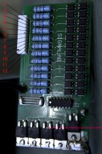
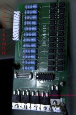
SIGNALAB (Ping) BMS Schematic

Just checked voltages again.
Bad cell has dropped below 2v. The others are fully charged.
Gotta face it, dead cell.

I'll see if I can get one from Ping with instructions on how to change it out.
 
one of my headway cells self discharged down to .80V but it came back to 3.65 when i charged it, holding 3.30 now.

if you had the BMS on the pack all the time you discharged, it may be ok.

eventually you will get a voltmeter and can measure the voltages exactly. if it is still about 2V i would think it is still ok, but you should charge it. the bigger concern is if you have been able to charge the other cells up to 4V.
 
dnmun said:
one of my headway cells self discharged down to .80V but it came back to 3.65 when i charged it, holding 3.30 now.

if you had the BMS on the pack all the time you discharged, it may be ok.

eventually you will get a voltmeter and can measure the voltages exactly. if it is still about 2V i would think it is still ok, but you should charge it. the bigger concern is if you have been able to charge the other cells up to 4V.
Thanks for the encouragement.
Hope springs eternal. I won't give up yet.
 
fechter said:
Interesting. The sample I have appears to be an older model.
Here's the top side: You can see there is an obvious problem here.
View attachment 5
Here's a closeup of the regulator chip:
View attachment 2
Here's the shunt transistor.
View attachment 3
These are the optocouplers:View attachment 4

Hi fechter:
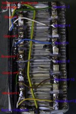
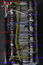
I have the same signalab Bms as you show in the picture, and my problem is I don´t know in which order do I have to conect the small wires of the bms conector to the cells of the battery. Can you help me with that?
My battery is a LiFePO5 36volt 15amp (Golden Motor), and trying to do some improvements I disconected all the wires of the batery and by mistake loose the photo I took before doing that. Now I have a Bms board, a conector with 12 little white wires, and a batery with 12 cells, how do I figure out wich cell goes to position nº1 of the conector, and hence to the Bms?
My knowledge of electronics and electricity is null, so please help me :wink:
Bateria.jpg
BateriaBMS.jpg
Thanks, Roberto
 
dnmun said:
you mean you took each of the sense wires out of the sense wire plug?
Well, really it was not like that but finally the old one was useless and in the new one all sense wires are white. I never thought it was going to be like this... :oops: If I ever imagen it was going to be this complicated....
I need to know according with the pictures attached:
my cell nº1 Yellow goes to position nº 1 in the Bms, it is TRUE OR FALSE?
my cell nº2 Green goes to position nº 12 or 2 in the Bms.
my cell nº3 Blue goes to position nº 3 in the Bms
my cell nº4 White goes to position nº 4 in the Bms
my nº5 Grey goes to position nº 5 in the Bms
my nº6 Blue goes to position nº 6 in the Bms
my nº7 Brown goes to position nº 7 in the Bms
my nº8 Grey goes to position nº 8 in the Bms
my nº9 Green goes to position nº 9 in the Bms
my nº10 Brown goes to position nº10 in the Bms
my nº11 White goes to position nº11 in the Bms
my nº12 Yellow goes to position nº 2 or 12 in the Bms ?

Now I have tried with 1.2.3...., but it doesnt work. When I measure before BMS I have 36.1volt, if I measure after the bms and conected to something, the voltage drops to 5.1volt. or something like that. It is possible to burnt the BMS if I change the pairs... or just it doesnt work?
The battery is a LiFePO3 36v15amp, I bougt to Golden motor. If anyone has one like this, I will appreciated very much if you could take a picture of your sense wires and their order in the conector, and another picture of the sense wires conected to the batery cells.
I hope someone can help me. Thanks, Roberto. :wink:
 
you are saying that you plugged the wires into the new BMS without knowing the sequence?

starting from the left side of the sense wire plug, the left or top wire goes to the top of cell#16 and then sequentially down from there. wire #2 to the top of cell #15 and so on. with the last wire going to the top of cell #1, all in sequence.

if you miswired the BMS and plug it into the battery then it most likely is toast. do you even have the sense wire harness plug? how do you connect the wires to the BMS?

this is the ping v1 signalab BMS, correct?
 
dnmun said:
you are saying that you plugged the wires into the new BMS without knowing the sequence? Yes

starting from the left side of the sense wire plug, the left or top wire goes to the top of cell#16 and then sequentially down from there. wire #2 to the top of cell #15 and so on. with the last wire going to the top of cell #1, all in sequence. Sorry but I don´t understand what you try to say to me. Could you please use the number I have in the pictures?

if you miswired the BMS and plug it into the battery then it most likely is toast. do you even have the sense wire harness plug? Yes
how do you connect the wires to the BMS? With a conector

this is the ping v1 signalab BMS, correct? I don´t know. I bought the battery to Golden Motor, and as you may see in the picture the only marking is SignaLab 0844

I am pretty sure the bms is out of order, since if I dont conected it , the bike work but if the bms is in the circuit, not even the lights goes on.
I took a measure of the diferent cell and there are 2 quite low. I dont know if to wait until I recieve the new BMS or if as someone has sugest to put it to charge in parallel with a light bulb of 21w and 12 volts.?
View attachment Cell Voltage.xls
 
if you paste that up here we can see which cells are low and maybe which wires are misplaced. but i already went through the sequence.

pin #1 goes directly to the top of the shunt resistor out in the middle of the board. so just measure starting there, each cell from top to bottom, that is #16 between the top of the first shunt resisotr and the second, cell #15 is the voltage between the top of the second shunt resistor and the top of the 3rd shun.... all the way down to #1.

did you already throw away the bms plug? how do the sense wires connect to the BMS?
 
dnmun said:
if you paste that up here we can see which cells are low and maybe which wires are misplaced. but i already went through the sequence.You can see the post up from here. The cell voltage table is above but I will post it again

pin #1 goes directly to the top of the shunt resistor out in the middle of the board. so just measure starting there, each cell from top to bottom, that is #16 between the top of the first shunt resisotr and the second, cell #15 is the voltage between the top of the second shunt resistor and the top of the 3rd shun.... all the way down to #1.Sorry but I dont know what you mean 1 goes to the middle of the board.... Could you please tell me: Sense wire 1 goes to signallab conector position nº 5...?
did you already throw away the bms plug? how do the sense wires connect to the BMS?[color=#008000]As I told you in my last post, Yes I hava a plug/Connector to the BMS[/color]


You talk about 16 cells, but I only have 36 small cell divided in 12 groups not 16

See files attached
View attachment Cell Voltage.xls
Bateria.jpg
BateriaBMS.jpg

Thanks :wink:
 
I have Ping 48V 20 AH BMS 2.5 and had exactly the same problem. I had a low cell that would not light up no matter how long I left 60v connected to the charging leads. I fixed it by charging the low cell by itself with this charger. http://www.batteryspace.com/smartch...lymerrechargeablebatterypack--ceullisted.aspx Now the cell lights up with the others after 60v charging.

Also, I had the same problem with my MOSFETS getting very hot during charging. I started putting a heat sink on the MOSFETS during charging. I use a CPU heatsink but I think most any will do. It is kind of clunky having to take the BMS out each charge to put the heatsink on the end of it but it charges just fine now.
 
Something really strange about that mosfet heating issue..

These mosfet are actually the IRF3205 that are rated 55V 110A 8mohm

I had confirmation from Ping that these mosfet are the IRF3205

BUT what i dont like is that the fresh fully charged battery go up to 60V on the 48V battery and charger.. :?


that's 5V over their max rated tolerance...

I just wonder if they might deteriorate and the junction just dammadge and the rds on could increase making them becoming more hot?

I notised that the Drain to source resistance have more than 1V while charging so at 5A charging current it need to dissipate 5Watts...


Doc
 
do you know that the charging FET is also a irf3205?

i wondered if it could be a different and higher resistance FET from the output FETs which i can also confirm are the irf3205 because i have seen the labeling on a few not completely sanded off.

charging voltage is much higher than discharge voltage too.

separately, irf3205 is also used in the cyclone controller for the output FETs.
 
dnmun said:
do you know that the charging FET is also a irf3205?

i wondered if it could be a different and higher resistance FET from the output FETs which i can also confirm are the irf3205 because i have seen the labeling on a few not completely sanded off.

charging voltage is much higher than discharge voltage too.

separately, irf3205 is also used in the cyclone controller for the output FETs.


Yes, these IRF3205 are also very popular and also used in the brushed crystalyte controller.

I think they probably use the same for discharge than for charge.. He suggested me to replace them with the 75N75.. ( the one also used in the shenzen controller..

Doc
 
very good choice and there are lots of them laying around from people upgrading their controller with 4110s.

why don't you see if you have an extra copper fin small enuff to fit and solder it on the end at the same time. you had that box of goodies, but you need something small, maybe just an L shaped section cut off another heat sink, solder it on top too. with the battery lead.
 
dnmun said:
very good choice and there are lots of them laying around from people upgrading their controller with 4110s.

why don't you see if you have an extra copper fin small enuff to fit and solder it on the end at the same time. you had that box of goodies, but you need something small, maybe just an L shaped section cut off another heat sink, solder it on top too. with the battery lead.


dnmun, I still think that instead of trying to dissipate the heat produced by the bad mosfet/desing choice it's better to try solving the problem directly instead of patching it.

Dont forget that a localized heat source very close to the battery will make the cell closer to it to have a lower internal resistor and the balancing and aging of these cell will evoluate differently. The thermal management of lithium battery is very critical and 5W heat source like a mosfet with let say 1 square inch surface can complicate the balancing job over the time.

The best is finding a mosfet that have the lowest rds on in DC and that can hold at least 60V

Doc
 
you are right doctor. treat the cause of the disease. sounds like you are already thinking 4110s.

i can't wait to see how hot mine gets when i charge it with that extra wire on there.
 
I was using a 4 amp charger when it got hot. Probably too much. Two of Mr. Ping's 2 amp chargers gave out on me and I couldn't find another one that small. His website said they were good to 5 amp, but I don't know.... Your thoughts?
 
Hm, my Ping V1 signalab BMS didn't heat up with a 10A charger hooked to it. Maybe I got an unusually good one. Or maybe it hasn't deteriorated yet from overvolting the FET, it's still pretty new. I wanted to see how fast it would start heating up, but I got room temperature all the way through a 10Ah charge. I was planning to upgrade to a 4110 anyway.
 
i finally got a v2.5 signalab working. i could detect no heat, none at all when charging with 3A for hours. nothing detectable with the finger right on the charging FET using this setup with the big wire soldered on. absolutely no warmth detected.
 

Attachments

  • DSC00665.JPG
    145.2 KB · Views: 2,037
I have just repaired a v2.5 16s signalab bms. It was from a friends new pack that failed for reason unknown and Ping sent him a replacement.
I replaced the charging fet with a 75NF75 and aok now.
I put it on my new builds' pack which has had a v1 signalab for a couple of months.
Interestingly the v2.5 bms took a further 12 or so hours until it was happy with the balance.
Love having those LED's as a quick visual to see what's going on! Numeric cell voltage readouts for the next version please :wink:
 
My new Signalab 36 volt BMS charges very cool at 4 amps (Bosch charger). It is the old style one.
otherDoc
 
Hi all new to this forum thing, but having trouble with a signalab bms v2.5 (not from ping) on my diy bike,
and can't find the schematic, just need to know what the 3 legged fet (or jfet as was told) are on the board,
one has blown labelled (N0100) in the row near the white balance socket, and keeps running down that string of batteries,
any help would be great as can't find a reference anywhere on the net, (sorry if done this wrong as am newbie)
 
Back
Top