SIGNALAB (Ping) BMS Schematic

Nope...this Signalab BMS was always out in the open but protected by a plastic see through case with plenty of air flow for the heat to dissipate.

It would melt the solder off the charging fet within 2 mins of charging on a 5A charger at 53.4v
 
@AW>>

the voltage across the mosfet when it shuts off the charge would be equal to the charger output voltage minus the full voltage of the pack. this is why i don't think the breakdown voltage is needed to be 100V. i suspect ping is using some kinda fet that has a BV of around 5-8V since he would assume that when the charge shuts off the difference in voltage would only be a few volts max.

with a pack that is severely unbalanced, which i assume most of these diy packs are, then there may be more voltage across the mosfet than the BV. so it leaks badly until the charging fet is turned back on, and that is where the damage to the mosfet takes place. make sense? just a guess, maybe someone who knows about mosfets can opine.
 
5A should be nothing for even a wimpy sized FET. One thing I've noticed on some of these is the gate drive for the FET is fed by a large (1M+) resistor. If the gate voltage is a bit low, the FET is not all the way on and will get super hot. In most cases you can measure the voltage from gate to source (two outer legs). It should be more than 5v but less than 20v. Around 10-15v will assure the thing is fully on.

Another problem could be when the FET turns off, it does so quickly, but turning back on after the HVC/LVC clears may be quite slow, resulting in high dissipation.
 
Hi guys. This is probably a bit late since you stopped discussing this last year but the reason that these FETs get hot is that the charging current goes through the diode in the FET - hence a 0.8 to 1V drop. When the FET is controlling discharge the current goes through the FET junction that is rated in mOhms.
 
JohnyV said:
Hi guys. This is probably a bit late since you stopped discussing this last year but the reason that these FETs get hot is that the charging current goes through the diode in the FET - hence a 0.8 to 1V drop. When the FET is controlling discharge the current goes through the FET junction that is rated in mOhms.

That would probably explain much or all of the heat problems.

However, if the BMS turns the FET on, then it doesn't use the body diode, it remains a switch that is on, and is then low-resistance. But I don't know whether this particular BMS does that or not.
 
There is a bank of charge FETs and a bank of discharge FETs. If all is working properly, both banks will be on so not much heating during charge. If the discharge bank is off, charge current passes through the body diodes during charge, so you would get a lot of heat.
 
Greetings gentlemen.

I hope this is an appropriate place to post my conundrum. I will need to replace a charge FET on my Ping BMS, but the lettering appears to be sanded off, so I am at a loss of what to do.

Situation: User error. Connected batteries in series before disconnecting parallel charger, resulting in a short.

Hardware: 2x Ping Ver2.5, 36v20Ah in series via Ping provided serial harness. 5A ping BMS, Current limited benchtop power supply 44.95v5.2A

Damage:
- Destroyed XLR plug on one battery (C- pin melted). I replaced the plug already.
- Cracked charge side Mosfet on BMS. See pic below

Diagnostics so far:
- Continuity checks out at all plugs.
- Charger is fine.
- Combined battery pack discharges normally.
- Batt A discharges and recharges normally.
- Batt B discharges normally. Each individual cell checks out, combined resting voltage at 39.3v.
- Batt B- Battery B will not recharge at all.
5A ping BMS short.jpg

You can see from the picture that at least two different types of FET is in use on the BMS board. Any ideas about what component I need for the charge FETS?
Thank you for your time - Tom
 
You don't need the exact part. In fact, there are many replacements that are probably better.
Depending on your local supplier, you want a MOSFET in a TO-220 package that has at least 60v and 50A continuous rating. I'd recommend replacing all the FETs on that bank to make sure they are matched.
One possible choice: IPP057N06N3

Since that's the charge side, you may also be OK with simply removing the blown one (try snipping the legs). If the others are OK, they can certainly handle 5A of charge current.

There is a chance the control circuit that drives the gate was also damaged. In this case, it may be nearly impossible to fix.
 
turn it over and take a picture of the traces going to the mosfet. if it is only the two in the corner, that would be the only ones you need to replace.

you can test the remaining mosfet with the diode tester on your voltmeter. if you put the meter to diode test and put the red probe on the source leg and black probe on the tab then you would see that they are shorted. the measured value of the body diode would be 0 mV.

then cut the source leg of the blown up mosfet so it is disconnected, and then remeasure the S-D body diode on the other mosfet next to it in the corner, with that one cut out, and if the remaining mosfet is functional it should show 530mV or so.

if they are blown open circuit they will both measure ---- open.

if they were shorted, it would expect the pack to charge so both are likely blown open.

you can measure the voltage on the gate leg of the charging mosfet to see if the opto transistors were damaged, and measure the gate voltage on the other, output, mosfets too to determine if the comparator that drives the gates of the ouput mosfets has been damaged.
 
Thank you for your help gentlemen. Diode testing confirms both charging fets as open line as you suspected Dmun.
I'll order up replacements as per your suggestion fechter. Cheers.

I shall report back when the replacements have been soldered in.
Gracias again.
-Tom

Edit: the charging fets all check out as not open.

EDIT2: replaced the fets. No dice. The gate voltage is off, so I'm assuming that the octocouplers are fried. Ordered a new BMS from Ping. 87USD shipped.
 
Hello,
I seem to have a problem with my signalab bms connected to a ping 24V battery. the battery charges and balances ok but when I connect it to my bike nothing happens. The leads coming from the battery indicate 28v after a full charge but the voltage drops to about 20V after the bms. when I connect it voltage drops all the way to about 2V. Voltage in on the mosfets is the same as battery voltage (28V) except for the one closest to the blue charging wire, this one has 14V on the leg nearest to the side of the board, the other leg has 20V. Anyone an idea what might be wrong. The battery is being used to power my lights in my velomobile (55W headlight, led taillight and led direction indicators). I already mailed ping about it but hoping to be able to mend it. Is it perhaps possible to draw power directly from the battery, bypassing the bms thus only using the bms for charging purposes?
 
Have you check all the cells for matched voltage ? with or without bms the cells should be close to the same voltage or check the balance of your pack. If without bms you have to go easier on it like discharge to 3.2v. or higher as to keep it from or just use half of it and recharge. But get a new BMS and then check the old one.
 
I have, the voltage is 3.5v, 7.1v, 10.7v, 14.3v, 17.9v, 21.5v, 25.1v, 28.7v, that's approximately 3.5v per cell. I have never fully depleted the battery, I once let the lights burn for about 4 hours and at that moment it was stille going strong. typically, I use my lights for about 2 hours max.
 
If you use to 25.5v or 26v and charge for now if you don't get a low cell below 3.2v. This is till you get the bms to be plug and play less checking and not a hobby. You need a bms either you or bms to monitor as youwill be the bms. Also put some extra sense wires for a 8s cellog after that easy brezzy for checking ect.
 
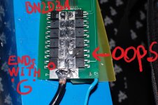
hi, i m trying to repair my signalab BMS. it is a newer version for lifepo4 with some changes to the scheme attached to the OP. Shunt regulator is now labeled "R2RU" and the ic for cell monitoring is "G4EH". I just damaged one or two channels and i don t know how to fix since the code on the ics semms to be non-existent. I just emailed mr ping, can please anyone help me?
 
how do you know they are damaged and how did it happen? is the mosfet still functional? that is usually what blows. i have spare parts too if you wanna take them off a pcb. i have some G4's also from bestechpower but won't give them up.
 
thank you for help. i replaced mosfet and caps but the impedence is still low and the led turn on for any voltage of the cell. It happened when the battery suddently disconnected from the bms. I can t know for sure what failed and i want to change all components :D. do you know the real name of these components?
 
hi, i have another stupid question!!!

i managed to find a signalab bms 20s in good working conditon (compared to mine). Wow that's very good news!

BUT

i only have 16 cells wired in series

how can i disable last 4 cells? i think that just shorting output of the last 4 optocouplers (i mean connecting the 16th input with the 20th output), both for upper and lower voltage will work.

any better idea?? :D
 
Yes, I would try that first. I don't think you could damage anything trying that.
Depending on the version, this may not work. In that case, it may be necessary to add a jumper to bypass the LVC output on the unused channels. A detailed picture of the board might help.
 
30m476b.jpg


29ncw3a.jpg


zn20b8.jpg


here you can see my old board and my new one. i managed to bypass LVC of hast cell of the older board (the 16s one) shorting the output of the optocoupler but i was not able to to the same with the HVC , thus i shunted the leads of the charge mosfet. Please don't blame me :D .


Now i m installing the new bms. IT is similar to the scheme in the OP but not exactly the same, the ic used to monitor the cells are not the same. But i hope the rest of the circuit will.

thank you for help.
 
update 1:

i shunted the optocouplers , only the LVC ones and the bms seems to charge just fine without touching the HVC ones. L'est wait full charge then i will try the discharge
 
I think you'll be OK with that board. Those used optocouplers for both the LVC and HVC. If you jumper across the unused cells, the optocoupler can't turn on.

Some boards have a different LVC setup that doesn't use optocouplers.
 
Back
Top