Switch mode supply mod

fechter said:
What are you using for a BMS?

My own design been running for a few years now on the UK BVS forum.

http://www.batteryvehiclesociety.org.uk/forums/viewforum.php?f=53
 
Nice. I remember that one now. That's more like the way I would have done it if I knew how to program microcontrollers a bit better.


On the current limiter circuit, I could do a run of boards if I thought there was enough interest to make it worth while. The board itself is the most expensive part. Fully assembled units are a possibility too, if I want to do some minimum wage work.
 
fechter you are lucky that the ic top did not put out your eye
 
fechter said:
On the current limiter circuit, I could do a run of boards if I thought there was enough interest to make it worth while. The board itself is the most expensive part. Fully assembled units are a possibility too, if I want to do some minimum wage work.

I'll take one, assembled or not...
 
You could use the inbuilt shunt on the meanwell supply, and pull power from the TL494, its even got a stable reference voltage (pin 14, 5v) to divide for your comparator. Err. Opamp. I take it you used an opamp vs a proper comparator for the lower speed/stability reasons?
 
heathyoung said:
You could use the inbuilt shunt on the meanwell supply, and pull power from the TL494, its even got a stable reference voltage (pin 14, 5v) for your comparator to divide for your comparator.

The problem is coming up with a version that works across the wide variety of models. The SP series, which seem to be the easiest to get, don't have shunts, or any sort of secondary current limit circuits. They just have the primary side "hiccup" mode.
 
If you guys want a low volume run of boards, make the circuit fit as many as you can on a 4x6" sheet of FR4 board, and I will have my CNC cut them out and mail them off to fetchter or gary or whoever wants them. I don't have tons of extra time though, so lets get the layout right on version 1.0, so I only have to mail them once. For some reason, I just HATE mailing things. :evil:
 
Adding a low impedance SMT shunt or a few in parallel on the outboard PCB would solve the issue of no internal shunt, then just the diff amp powered by the TL494 reference voltage should suffice.... no?
Though if were monitoring the low side of the DC output < 66v or so... those allegro Hall Current Sensors could be quite useful and fully isolated :)

-Mike
 
fechter said:
Dang! those brain cells are dying fast these days.

Funny, I think the SP-320-24 I'm testing with is the very same one Methods was using (he sent it to me).

I have 3 of them on hand here in 24v and several more of those "Astro models" in 48v not from Methods, using them slightly modified to prevent hiccup mode at 120% power output and have a switch to drop them into the 12-16v range for 6S RC Chargers, 20-36v for - well you get it :)

Do test with the S-350-24/48 models you have on hand... if they pop, I'll dispatch replacements :)

-Mike
 
mwkeefer said:
Adding a low impedance SMT shunt or a few in parallel on the outboard PCB would solve the issue of no internal shunt, then just the diff amp powered by the TL494 reference voltage should suffice.... no?
Though if were monitoring the low side of the DC output < 66v or so... those allegro Hall Current Sensors could be quite useful and fully isolated :)

-Mike

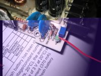
The point, however, is to make something that is easy to install, across all models. This variant simply requires one wire be added right in the front, next to the voltage adjustment pot. The total parts cost, even with the "extra" regulator bits, is just a few dollars.

-- Gary
 
Makes sense to me :)

A LM317HV has a differential voltage of 60V so you could potentially use one of these up to 70V input (no pre-reg needed) as opposed to the 7812. TBH I'm interested in the choice of an opamp vs comparator (opamps make lousey slow comparators). I'm not nitpicking, just interested...
 
I used the op amp since it was handy. I've also found if it's a little slow it reduces the tendency to oscillate, though the compensation network built in to the power supply should handle that. For a battery charger, the load does not change quickly.

Is there a TO-92 version of the HV regulator? I'm using the small stuff since the op amp doesn't draw much current. The pre-regulator approach works fine too, and doesn't add that much to the cost.
 
Nope but there is a TO-39 - much smaller than a TO-220. Since you aren't pulling much current, its fine without heatsinking.

http://www.national.com/ds/LM/LM117HV.pdf

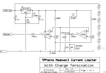
It would be simple to add charge termination for the purely CC/CV cell users - eg. Konions (this is actually pretty much the current termination setup I use - except mine uses a LM393 - which is open collector - and adds some extra complexity due to this - the opamp works better here)

Meanwell_Limiter.jpg

Also reduces the component count when removing the pre-reg and replacing with the 317HV - 60V differential means a 72V max input, or if you increase the rail voltage close to the maximum of the LM358 (30V) you could squeeze it up to about 85V. Next step would be the TL783 with a 125V max differential for the criminally insane amongst us! But they have a minimum current load that has to be adhered to, and a high dropout voltage (spec sheet says 20V but in reality its closer to 15). So they need some heatsinking.
 
so "RH" sets the CC current limit. "RL" sets the minimum current after which the charger cuts out to terminate charging.

i like it.

only issue - have you checked the prices on the LM317HV in the TO-39 can? costs wa more than the rest of the circuit put together.

rick
 
Hey, I like it!

A couple of things to keep in mind:

At higher voltages, most people would be using multiple supplies in series, so the voltage regulator only needs to handle the output of the supply to which it is connected.
The cost of the pre-regulator parts is less than $.50 and it's only 3 parts.
If you want to be really cheap, you could tap into the auxiliary supply inside the Meanwell (Vcc on the TL494), but that would be extra work to find the right spot and add a wire.

With just the op amp, the circuit power consumption is very low, so a small regulator will suffice. Driving the LED increases the power consumption a lot, but if a high efficiency LED is used, you can run it a a couple of mA and still see it.

You could tie in an opto coupled HVC signal from a BMS to pull up the voltage sense line. This would throttle the current to prevent cells from going over.

The value or RL should be lowered to reduce the adjustment range. We don't need 0-15 amps range. 0 - 1.5 amps would be more appropriate. Just make RL 100 ohms instead.

Depending on the gate threshold of the FET, you might get away without the 10k to ground, as the LED will pull it down to less than about 2v.
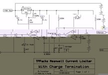
This is essentially how the control circuit works on the latest BMS circuit I'm working on, so I haven't considered adding it to the limiter but it would make sense for people who aren't running a BMS.
 
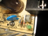
OK, back at the lab, I did some work on the S-350-24. Stock output was about 27.5v at maximum adjustment. This is just a little too low to work for 8s worth of LiFePO4 or a pair of 12v SLA. Lowering the value of R25 increased the max voltage up to the limit set by ZD1. Since I'm lazy, I was able to mod the board without removing it, which is a pain. Using a very thin flush cutting snipper, I was able to snip one side of ZD1 with the board in place.S-350 ZD1 cut.jpg

Since I want lower the value of R25, I can just add another resistor across the one that's there from the top.
I used a 10K and bent the legs to hook onto R25. With 10K across R25, the maximum voltage increased to around 32v, which is just right for me. View attachment 4
S-350 resistor mod 1.JPG

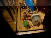
After hooking it on, I bent the hooks up to hold it in place while I soldered it. Here's after soldering:S-350 resistor mod 2.JPG

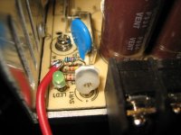
Since one side of R25 is the voltage sense, the added resistor makes a handy spot to attach the voltage sense wire.S-350 voltage sense wire.JPG

I did some testing with a big resistor. Sorry I can't remember who sent that one to me, I think it was Methods, but it's a honker. And it gets really really hot!Big load resistor.JPG

Limiting action seemed to work perfect within the conditions I was able to set up.

So it is possible to do pretty much everything without lifting the board out.
 
Wait! there's more!
Sorry if this is already posted in the thread somewhere. It takes too long to read everything. I should make a Meanwell Reference thread sometime.

this is the SP-320-24
The voltage adjustment pot and resistor are in nearly the same place as the S-350.
Stock voltage at maximum adjustment was 27.36v on this unit. The maximum voltage is set by R73.
Without disabling the overvoltage protection zener, the highest you can go is 28.2v, at which time the unit shuts down completely and you have to cycle the power to get it back on again. This is a 'crowbar' type over voltage protection that is held down by an SCR.

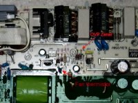
To disable the overvoltage protection (OVP), you can snip ZD7 or ZD8. ZD7 and 8 are in series on my unit. Adding a 5v or whatever zener in series with the existing ones would be safer than just snipping it.

The fan thermistor is located nearby, and can just be shorted out to make the fan go full speed.
SP-320-24 OVP zener.jpg


Like the S-350, I added a 10K resistor across R73 and this got the voltage up to 31.5v. Since the output caps are rated for 35v, I would not suggest going any higher than that.SP-320-24 voltage adjustment.jpg

Testing with my add on limiter circuit worked OK. No smoke this time.
 
fechter said:
Hey, I like it!

A couple of things to keep in mind:

At higher voltages, most people would be using multiple supplies in series, so the voltage regulator only needs to handle the output of the supply to which it is connected.
The cost of the pre-regulator parts is less than $.50 and it's only 3 parts.
If you want to be really cheap, you could tap into the auxiliary supply inside the Meanwell (Vcc on the TL494), but that would be extra work to find the right spot and add a wire.

Yep - Vcc on a TL494 is pin 12. I havn't measured Vcc on these yet (or measured how stable it is) bear in mind that the TL494 is capable of sustaining an absolute maximum voltage of 40V as opposed to the 35V IIRC of the opamp. If you were using the TL494 Vcc I would strongly recommend also using its stable +5V reference voltage (pin 14) for the comparator as if you use the VCC (which is indirectly derived from the output - its bootstrapped) and you vary the output voltage, you vary your reference voltage - less than ideal.

fechter said:
With just the op amp, the circuit power consumption is very low, so a small regulator will suffice. Driving the LED increases the power consumption a lot, but if a high efficiency LED is used, you can run it a a couple of mA and still see it.

Yep the resistor I specified would run at 10ma for a 1.2v Vf LED - a high brightness LED would be quite visible at 2.5ma or less.

fechter said:
You could tie in an opto coupled HVC signal from a BMS to pull up the voltage sense line. This would throttle the current to prevent cells from going over.

The value or RL should be lowered to reduce the adjustment range. We don't need 0-15 amps range. 0 - 1.5 amps would be more appropriate. Just make RL 100 ohms instead.

Yes, I forgot to revise that value on the schematic, it was a quick-and-dirty job :)

fechter said:
Depending on the gate threshold of the FET, you might get away without the 10k to ground, as the LED will pull it down to less than about 2v.
Theoretically the LED would pull it to its Vf voltage, but I figure better safe than sorry!
 
Here are the two revised schematics:

Schematic v 1.1 I somehow missed the current limiting resistor for the Vsense line. Oops. Also revised the resistor values for the LED's to reduce current draw to 2.5ma - so use high brightness versions. Also added (optional) an indicator for CC mode - not strictly neccesary but I have this on the Makita charger at work and its a good indication of where the charge process is up to.

Meanwell_Limiter V11.jpg

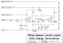
Schematic v1.2 removes the voltage regulator section entirely and uses pins of the IC (which are easy to solder to with small hookup wire) for power and also a stable +5V reference (so the resistive divider resistors have changed - 91K rather than 220K).

Meanwell_Limiter V12.jpg

Bear in mind that I got up at 3am this morning so if there are any minor errors this is probably why...

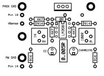
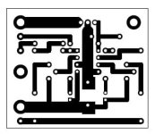
And here is the PCB artwork PCB.jpg

EDIT - There is an error on the board - MOSFET gate is meant to go to pin 7, and there is meant to be a switch between pin 8 and the mosfet gate - oops.

...and silkscreen...Silkscreen.jpg
 
I received one of the three S-350 clones I ordered on Ebay.

The one I got today is from this seller:
http://cgi.ebay.ca/New-24V-DC-14-6A-350W-Regulated-Switching-Power-Supply-/120589302236

Its quite different than the other S-350 clone I already have and I haven't seen a similar one in this thread so I thought I'd share some pics.
As you can see there are a lot less components on this board and there is a little PCB mounted vertically to the main board in the corner where you usually have the R33 resistor.
View attachment P1030179.JPG
View attachment P1030180.JPG

Disappointments:
- There were a lot of loose solder blobs inside the supply
- AC switch was set to 220V (good thing I cought that one before plugging it in!)
- The voltage range is too low for this model (18.6 to 23.3V instead of 20-26.5V)
- Hooked up my iCharger 206B on it and was only able to get it to output around 160watts as opposed to the 300watts I get with my other S-350 clone

The 160w output means there is some sort of current limiting going on, but unfortunately its too low.
 
I can't ID the chip but it's the replacement for the TL494CN in SMT format - there are 2 shunts between the caps and the coils and I'd bet just about anything if you trace them back they go to the SMD opamp (to the left of the other IC).

Can you take a better res image of the "daughter card"?

-Mike
 
Same design as meanwell - tl 494 just smd.
-Mike
 
heathyoung said:
Here are the two revised schematics:

Schematic v 1.1 I somehow missed the current limiting resistor for the Vsense line. Oops. Also revised the resistor values for the LED's to reduce current draw to 2.5ma - so use high brightness versions. Also added (optional) an indicator for CC mode - not strictly neccesary but I have this on the Makita charger at work and its a good indication of where the charge process is up to...........

Nice.

Being a cheap ass, I would also recommend using a common divider for both amp sections. The 91k or 220k could feed both RH and RL in series. You'd never want your limit current to be lower than the cutoff current. Saves a resistor and reduces power consumption a tiny bit.
 
Back
Top