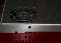
Switch mode supply mod

Thats a good idea, means setting is more obvious.
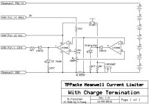
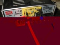
Meanwell_Limiter V13.jpg

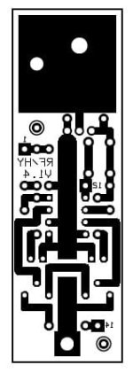
This board is 51mm X 43mm, and is designed to fit inside the meanwell power supply top cover with only the LED's and the start button poking through. The trimpots are accessible through holes in the case as well. The Mosfet is heatsinked to the case, and the shunt is an SMD version, so the heat will be distributed through the tracks on the PCB as well. Oh and I fixed the issues with the wrong tracks :)
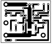
Meanwell_PCB_V13.jpg

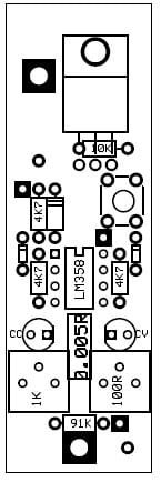
Here is the component placement: Everything bar the shunt is mounted as usual, the mosfet is bent so its back mounts to the underside of the meanwell cover (with a silicon insulator etc). It is screwed to the cover as well for secure mounting.
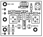
Meanwell_Silkscreen_V13.jpg

And the parts list is pretty straightforward.

1 X BOURNS - 3386P-1-101LF - TRIMMER, 100R
1 X BOURNS - 3386P-1-102LF - TRIMMER, 1K
1 X MULTICOMP - MC32830 - Tactile Switch
1 X WELWYN - OARS1 - R050FI - RESISTOR, SMD 1% 0R050
3 X 4K7 250mW Resistor
3 X 0R 250mW Resistor
1 X 10K 250mW Resistor
1 X 91K 250mW Resistor
1 X LM358 Dual Opamp
1 X Red High Brightness 5mm LED
1 X Green High Brightness 5mm LED
2 X 1N914 Diodes
1 X IRF2907 75V75A Mosfet

I'll knock up some boards this afternoon or next week if I get a chance... I need something to charge up 52V worth of konions :)
 
That looks great now.

The FET won't get super hot, so heat sinking to the case might not be worth it. I've used about a 10mm x 20mm pad on the board to serve as a heat sink for IRFB4110s running 15A with not too much heat. I just solder the tab to the copper.

If you need to pull the top to work on it, you may want an easy way to detach it.

As I mentioned earlier, it would also be real easy to interface to the HVC line from a BMS. It would tie in between the 12v line and the cathode of the diode going to the sensing line.
 
Another way to do it would be to lower the CV voltage when the low current comparator trips. This is how some of the high end lithium chargers work, as well as many SLA chargers. If the voltage drops to a safe "float" voltage, current into the cells effectively stops. This would eliminate the need for a FET that takes the full current. Tweaking the CV voltage would take a resistor from the output + to the voltage sensing line to lower the output voltage. This could be done with a solid state relay or just a small FET.

This could also eliminate the need for a start button. If the pack is below the float voltage, it will draw enough current to bump the CV setting back to the high state and the charge cycle begins.

I'll try to draw it up.

Meanwhile... the first batch of current limiter boards is in the mail. I should have something to play with soon.
 
I decided the board I designed (and it has an error - oops again) while it works, is way too big to be practical to be mounted inside a meanwell.

There is very little in the way of free space in these, so you only have about 25mm high X 75mm long for the PCB, and max 10mm thick, that fits right near the transformer and the TL494. Added bonus is that the way I designed the board, you don't need to unplug it when you take off the lid, the leads are short to the TL494 and the shunt and mosfet are fan cooled! :)

Meanwell_PCB_V14.jpg

Here is the latest design, I'll put it to board tomorrow (thank goodness for positive photoresist coated boards, means PC to PCB in under 1 hour!) Longest wait is for the next-day delivery from Farnell.

New board is 25mm X 75mm, with no 0 ohm links this time (that was a bit lazy) and single-sided.

Meanwell_Silkscreen_V14.jpg
 
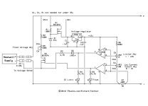
Here's the schematic for what I was describing earlier. All of the parts are small/cheap. When the current drops below the low current set point, the output voltage will drop from the normal CV setting to a lower float setting. This will stop the charging current without needing a big FET to switch it off.
The resistor values for R2 and VR1 are somewhat wild guesses based on a 24v unit and about a 2v decrease when it goes to float. For a 48v unit, R2 would need to be about twice as big (I thinK), but I've never actually seen the guts of a 48v one, so it's a guess.

After discharging the pack, it should be below the float setting and the current draw should be enough to kick it back into the high setting. Fully automatic start.

The LEDs are optional, but would indicate hitting the CC limit and going to float (end of charge).

Likewise, the voltage regulator is optional if you want to tap into the supply to pick up the voltages. I'd prefer to have some extra circuitry and avoid attempting to solder onto the right spots inside the supply. Not all of them use a TL494 chip either.
Limiter 5 schematic.jpg
 
Well, the mini limiter boards came in the mail today. Assembly is not bad at all. The board fits nicely on the terminal block and NO SMOKE came out of anything. I think this is because I was chicken and used a socket for the chip.

After a bit more torture testing, I should be able to offer these both as bare boards or fully built. I'll start a new thread in the 'For Sale' section when I get everything ready.
View attachment 1
Cute little bugger :wink:
Here is how it looks installed:
4.2.3 Limiter board installed.JPG
 
Very neat!

It's much smaller than I thought it would be.

I've modded my Meanwell clone by cutting/grinding the shunt. Got it down to 350 watts, but its buzzing like hell and its driving me nuts. Hopfully by moving the current limiting to this little board instead of the PS the buzzing will go away.

I'll buy one!
 
Nice. Personally I would prefer an SCR to the Mosfet, so when it hits the end of charge it turns itself off. I'll probably keep with the Mosfet at the moment because I have heaps that are suitable.

Waiting for the parts to turn up from Farnell this morning...
 
That's a neat little circuit, the terminal block mount is a nice touch too. Good work!

fechter said:
The board fits nicely on the terminal block and NO SMOKE came out of anything
This is always a bonus.
"introducing the new Sony 100" 3D LED TV - Full HD resolution and no smoke comes out when you turn it on!" :lol:
 
No buzzing so far, but I haven't fully loaded it yet. I need bigger resistors :twisted:
Actually, I have plenty of batteries to try it out on, but it will take a bit of work to set everything up.
It behaves real nice at very low settings, like 2A too.
 
I would be interested in one of those boards Fechter, that's a very neat lil package.
 
I think this should totally avoid the buzzing problems encountered with tweaking the shunts. I'm working on getting some parts, instructions, etc. Hang in there, it will take me a little while to get set up.
 
Nice - I didn't think of using the terminals on the back, I mounted it inside the case so it blended in with the original design (and couldn't get knocked about in the panniers)

Also - something to consider - I ended up putting a 5.1V zener across the output to the voltage sense (pin1) of the TL494 - its only expecting a maximum of 5V (the reference voltage) and hitting it with 12v is a little cruel. It normally sits at 2.5(ish - 0.5 X Vref) steady state so 5V is still overkill. What do you expect from an EE with OCD.

Here is my version... It lives in a very cramped spot under the fan (so the shunt is fan cooled, as is the mosfet) - there are 3 wires from the TL494 pins, pin 1 (Vsense), Pin 12 (Vcc - which is anything from 16-22V) and pin 14 (Which is Vref - 5V).

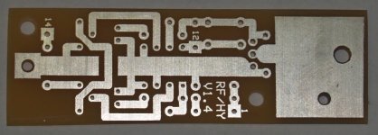
Here is the PCB - before anyone mouths off about paper phenolic boards, they are 1/3rd of the price of fibreglass and a lot easier on tools.

Unpopulated:
Unpopulated_Small.JPG

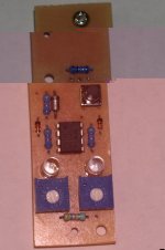
Populated - Top side - LED's are high brightness, and they really mean it. DSE had a runout on LED's, so the really bright ones (16,000mcd) were 50c each.

Board_Top_Small.JPG

Bottom Side - Using an OARS 0.005Ohm 3W surface mount shunt - Nice and easy to solder, and takes up bugger-all room.

View attachment 3

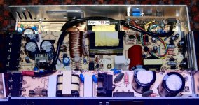
Top view of inside of meanwell power supply with module installed. 12ga wires from the side of the shunt, through the board and off to one of the screw terminals that has been snipped at the board, bent up and is soldered to. Works well, and allows only one terminal to be CC/CV controlled.

Internal_Wirning_Small.JPG

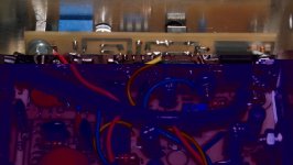
Yep its tight in there alright! But it fits...

Close_Up_Small.JPG

And the installed, side view. Top pot is Lower Current Limit setting (ie. when in CV mode, when the charger disconnects from the batteries - eg. Konions at C/20) Green light (top) is on when in CV mode. Bottom Pot is Upper Current Limit - when in CC mode, both RED and Green LED's are on. When charger is finished, it disconnects the load from power, but it does leave a small load through the LED (due to the reverse body diode in the mosfet) - removing the LED would reduce this current to nearly zero.

Side_View_Small.JPG

Only mods to this supply are the removal of the thermister and replacement with a 1K resistor so the fan is always on.

PS - sorry about the crappy quality of the photos, the originals were 5M each (8mp macro images) resized badly... Not sure why some wont show inline - probably a bit big?
 
Is there any secondary logic that turns off the fan, besides the thermisitor? Reason I ask is because I did the fan mod(removed thermisistor and replaced with two paralleled 1K Ohm 1/4W resistors = 500 Ohm 1/2W.) The fan comes on as soon as it is powered up, stays on during the entire charging process, but cuts off when the amps go down to zero. Does anyone else experience this? No complaints, as it actually seems to be more efficient, since the fan stops using power. Just curious.

BTW - This is an OEM MeanWell S-350-48.
 
Nice job on the control board. Now to see if it works.
The inputs to the TL494 can handle up to Vcc, so I didn't worry about clamping it, but that can't hurt.

On the fan, yes I noticed the same thing. At no load, the fan stays off but automatically comes on when there is some load.
 
Yep it works well, I charged some very empty 18Ah SLA's at 4A and terminated the charge at 1A - no muss no fuss. Now I will have to do this for my charger at home (I keep one at work and one at home so I don't have to carry one with me).
 
Nice. :wink:

I'm going to try scratching up a version that goes to float instead of disconnecting the pack. This eliminates any high current stuff on the board.

The terminal block mounting is surprisingly sturdy, but does leave the board exposed.
 
About this stuffing around with the thermistor value to have the fan always on.

Looking at the reverse engineered circuit posted by Kingfish: (thanks for that BTW)

The thermistor drives the second op-amp in U2, which turns the fan on.
It also drives the first op-amp (U2 pin 5 connected to U2 pin 3).

The output of the first op-amp in U2 (pin 1) goes via D19 & R45 into DTC (dead time control) on the TL494.

So clearly, the effect of rising temperature is that the fan comes on, then the TL494 starts shortening it's pwm via the DTC.
I suspect this is why some people are getting buzzing, or even complete shut-down.

I suggest a better way to have the fan always on is to remove Q5, and link out Q5 collector-emitter.

Unfortunately, I can't test this yet as my S-350-48 is still on a slow boat from China.

Amanda
 
Hi
i have just picked up a 12 cell balance module that goes between a lithium non balancing charger and the battery pack, it has in the instructions max input of 10A there may be a little leaway but that would require changing the fuse in the device, something to try if things work.
my question is will this board that factor is doing or any other board prvide a current control so i can set the amperage output to 10A instead of the 18+A that a pair of 24V meanwells can put out.
at the moment i will use a 48v supply that puts out about 7.5 A,less than the 10A limit.

Geoff.
 
Absolutely. The Mini-Meanwell limiter board can reduce the current to any level you want.

By lowering the current limit significantly below the maximum rating, heating issues will be much improved and the fan mod may be unnecessary.

I'm working on getting parts sets for them and should have them ready to go soon.
 
Hi fechter when the board is perfected have a word with me, I can get keywin to make up the boards in china, they could be added on to another order to make it cost effective.
Keep up the good work.

Geoff
 
commanda said:
I suspect this is why some people are getting buzzing, or even complete shut-down.

This is consistent with the behavior I observed with my S-350-24.

I've current limited it to pretty much exactly 350watts by grinding down one of the shunts. It will remain quiet until it gets hot enough for the fan to kick in, then all hell breaks loose. The buzzing remains if I unplug the fan. Same behavior with the resistor mod on the thermistor.
 
i noticed that the chinese at final test during assembly will modify the shunts on the controllers to get them down inside the 20A spec by crimping the shunt wire with dikes. sometimes there are 3 small notches(i have seen some deep ones too) in the shunt where they used the dikes to reduce the thickness of the shunt in the notch and that pushes up the resistance, and effectively lowering the amount of current the controller will allow.

so maybe just take some dikes and keep crimping a little at a time until the current drops enuff to stop the buzzing.
 
commanda said:
About this stuffing around with the thermistor value to have the fan always on.

Looking at the reverse engineered circuit posted by Kingfish: (thanks for that BTW)

The thermistor drives the second op-amp in U2, which turns the fan on.
It also drives the first op-amp (U2 pin 5 connected to U2 pin 3).

The output of the first op-amp in U2 (pin 1) goes via D19 & R45 into DTC (dead time control) on the TL494.

So clearly, the effect of rising temperature is that the fan comes on, then the TL494 starts shortening it's pwm via the DTC.
I suspect this is why some people are getting buzzing, or even complete shut-down.

I suggest a better way to have the fan always on is to remove Q5, and link out Q5 collector-emitter.

Unfortunately, I can't test this yet as my S-350-48 is still on a slow boat from China.

Amanda

Yep thats the best way to do this - there are some errors in the circuit BTW - I found a few when I was repairing the meanwells I had. Its more to do with the pulse transformer section that I found, but keep an eye on them and trace yourself.

Dropping the voltage when the batteries is full is a good way to end the charge cycle, but I think I would still prefer a SCR to lockout when done.
 
heathyoung said:
Yep thats the best way to do this - there are some errors in the circuit BTW - I found a few when I was repairing the meanwells I had. Its more to do with the pulse transformer section that I found, but keep an eye on them and trace yourself.

Dropping the voltage when the batteries is full is a good way to end the charge cycle, but I think I would still prefer a SCR to lockout when done.

so would you just replace Q2 with an SCR? it would latch on and conduct until the Meanwell is turned off. but for proper operation would you not also need a blocking diode in series with the (+)? otherwise as soon as you connected the battery you would power up the circuit and lock the circuit into the float mode without having a chance to charge?

rick
 
Back
Top