El_Steak
10 kW
I'm about to order my additional power supplies.
My pack is 24s Lipo, so I need 100V and 1400Watts would be cool.
I currently have one S-350-24 (clone). I could simply buy 3 more 24V models and be done with it, but I thought it may be more useful in the long run to buy different voltage models. Perhaps a 12V, a 15V and a 48V. This (plus my current 24V) would give me the same 100V / 1400W charger but could also be reconfigured for pretty much any possible voltage under 100V should I need it for other projects.
Am I looking for trouble putting 4 different voltage models in series ?
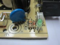
BTW, on my S-350-24 clone model, adding a 1K resistor in parallel with the existing thermistor did the trick for the "always on" fan mod.
My pack is 24s Lipo, so I need 100V and 1400Watts would be cool.
I currently have one S-350-24 (clone). I could simply buy 3 more 24V models and be done with it, but I thought it may be more useful in the long run to buy different voltage models. Perhaps a 12V, a 15V and a 48V. This (plus my current 24V) would give me the same 100V / 1400W charger but could also be reconfigured for pretty much any possible voltage under 100V should I need it for other projects.
Am I looking for trouble putting 4 different voltage models in series ?
BTW, on my S-350-24 clone model, adding a 1K resistor in parallel with the existing thermistor did the trick for the "always on" fan mod.