The dreaded Error 30 (communication error) [Resolved]

rick_p

100 W
Joined
Feb 16, 2021
Messages
260
Location
Los Angeles
I'm helping a neighbor diagnose his bike, which displays an Error 30 a few moments after you power on the bike. I found dozens of posts about this particular error across several websites, videos on YouTube, and a troubleshooting guide on the bike manufacturer's website. So, I really didn't think I would need to ask for help here, but I have tried everything I can think of, so I'm seeking suggestions.

Bike: 2018 AddMotor folder with 20" wheels.
Motor: Bafang 500w rear hub motor
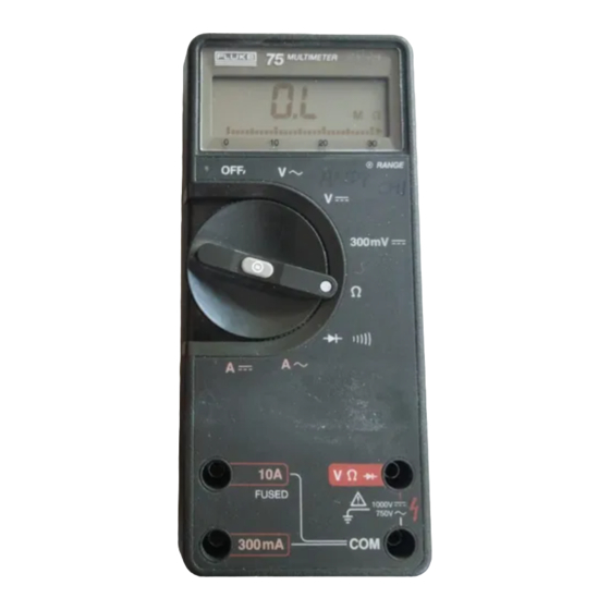
Display: AddMotor branded but I'm about 99% sure it's a Kingmeter SW-LCD
Controller: Lishui LSW 1250
Battery: 48v

What I've tried thus far:
  • Per the manufacturer's troubleshooting guide, I disconnected everything, then connected only the battery and LCD to the controller and turned it on. Same error, so that rules out brakes, throttle, light, and motor.
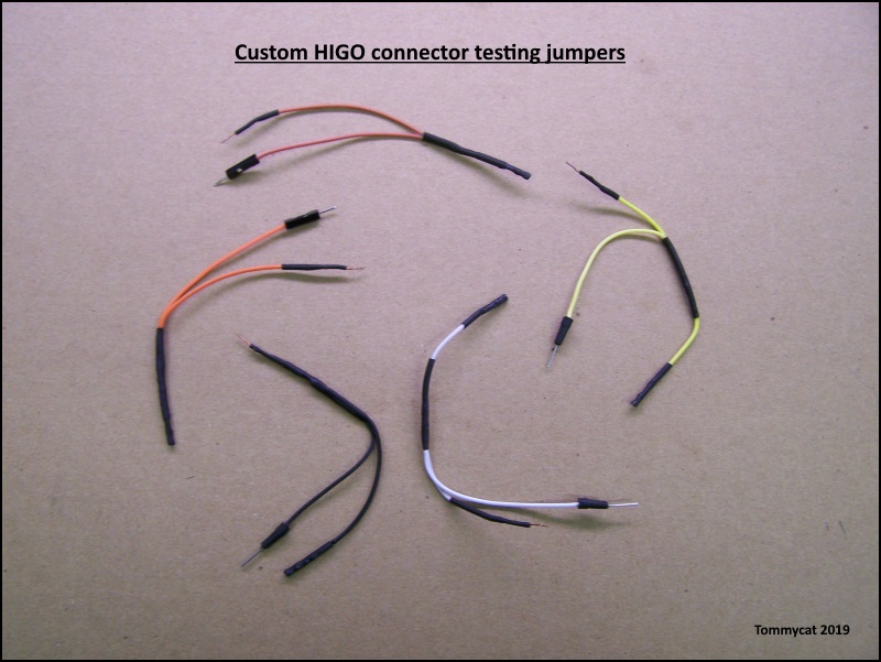
  • Since the most frequent cause of this error is wiring, I removed the harness from the bike and verified each pin of the LCD connector (display end) has continuity (at least 5 ohms resistance) at the controller end of the cable with no short circuits to other pins.
  • I changed the controller to a newer model, with only the battery and LCD connected and turned it on. Same error, so that sort of rules out the controller unless it just instantly fried a second controller. (as it turns out, that is not a definitive test. In the end it turned out that the display and the original controller were both fried, so getting the same error with the new controller did NOT rule out the original controller also being bad. Note added after resolution.)
  • I didn't have a spare Kingmeter SW-LCD but I did have a spare SW900 so I wired that up. It displayed an Error 10, which is also a communication error a few moments after I powered on the bike. (Not a good test though, not all displays work with all controllers. Note added after resolution.)
  • I reconnected the original LCD and did the reset procedure on it (simultaneously hold up and down buttons) and reset all the settings to what seemed like default settings. No difference, same error 30.
It may be worth mentioning that if I connect the throttle and motor cables, the motor works until the display shuts itself off and kills power to everything.

Any and all guidance/suggestions is greatly appreciated. Thank you in advance.
 
Last edited:
Solution
A Summary of this entire thread, with links to key information when diagnosing an Error 30:

I read through the entire thread and added notes and corrections wherever possible to help prevent misleading anyone trying to diagnose their bike for an Error 30 condition.

Key Post: KT and Lishui wiring sequence diagram, and voltage readings indicating abnormal reading on Yellow (TX) wire.

Next post is also good, it shows both KT, Lishui, and Bafang) configurations. Pay attention to male vs female configurations.

Helpful post if you're working on an Add Motor bike with proprietary harness and controller.

Helpful post if you're working on an Add Motor bike with proprietary harness and controller. Same as...
I'd still feel a bit uneasy with full battery power apparently on two pins, when it should only be on one. (Display disconnected right?)
I am concerned about full battery power on two pins, very concerned now that you have confirmed it is not normal. Yes, the display is disconnected. I didn’t get around to testing the jumper today, I was too busy preparing for this big rain we’re supposed to get.
Wouldn't you want to get to the bottom of this first? Perhaps you have a bad harness cable... Are they ghost voltages?
Yes, I very much want to get to the bottom of this. Regarding the harness, I removed the harness from the bike and verified each pin of the LCD connector (display end) has continuity (at least 5 ohms resistance) at the controller end of the cable with no short circuits to other pins. However, I did not check the other connectors (brakes, light, throttle) so I’ll check all of those tomorrow while it’s raining. By “ghost voltages” do you mean that it might drop to zero if there was a load (actually connected to something)? If so, I’m not sure how I could test that.
Find the true ground pin hole, or use battery negative for retesting the pin hole voltages...
I wanted to do that the first time but the way this bike is setup that’s not easy to do, but I will absolutely do it that way and confirm the ground pin hole this time.
 
Last edited:
I was too busy preparing for this big rain we’re supposed to get.
Hope everything goes well for everyone.

By “ghost voltages” do you mean that it might drop to zero if there was a load (actually connected to something)?
Exactly, a well described definition by you.

My best example: My battery will show say 52 vdc output when "on". But also, 32vdc when turned off. When on, powers bike. When off, just pressing the battery's led power indicator light button will discharge ghost/phantom apparent voltage potential to zero.


If so, I’m not sure how I could test that.
A 60 volt load supplied by suspected voltage and battery ground, that would pull less than 2 amps. I'm thinking. 60 volts to handle the possible voltage potential. The 2 amps to keep it under the current capacity of a lot of Ebike cable ratings.
A DC bulb or small dc motor recovered from a battery powered device. I've also seen AC light bulbs (incandescent) used to test Ebike battery chargers for output... see THIS POST.

Stay with the Egg rider pin layout diagram to keep everyone on the same page. As always mirror pin labeling when changing from male to female side or visa versa... :) This has caught me more than once... :-/


very concerned now that you have confirmed it is not normal.
Not entirely sure, but with all the different pin scenarios used, more concern from which pins it was being read on.

If someone with a functioning KT controller would mind taking a few voltage readings and weigh in here... E-HP, I'm looking at you. ;)
 
Hope everything goes well for everyone.
I'm in west Los Angeles, we're not getting anything different than we got all winter, but I hope all is well for the folks east of us who are getting a lot more rain than us.
A 60 volt load supplied by suspected voltage and battery ground, that would pull less than 2 amps. I'm thinking. 60 volts to handle the possible voltage potential. The 2 amps to keep it under the current capacity of a lot of Ebike cable ratings.
A DC bulb or small dc motor recovered from a battery powered device. I've also seen AC light bulbs (incandescent) used to test Ebike battery chargers for output... see THIS POST.
Would this work, or will it just pop instantly because it's only rated for auto 12 volts?
12v-bulb.jpg

Stay with the Egg rider pin layout diagram to keep everyone on the same page. As always mirror pin labeling when changing from male to female side or visa versa... :) This has caught me more than once... :-/
Exactly what I did, same exact pin layout, just mirrored for female connector.
Not entirely sure, but with all the different pin scenarios used, more concern from which pins it was being read on.
If someone with a functioning KT controller would mind taking a few voltage readings and weigh in here... E-HP, I'm looking at you. ;)
The "near" battery voltage reading was being read on pin 3, Yellow (TX), display data transmission line.
 
Would this work, or will it just pop instantly because it's only rated for auto 12 volts?
With old incandescents, it is about the current flow thru them and their resistance (hence total wattage creating heat) rather than voltage. The voltage induces the current across them, so higher voltage means higher current for the same resistance...

Initially when the filament is cold it takes a pretty low current to turn it on but as it heats up it's resistance increases...it makes a kind of PTC resistor.

Most of the inrush current limiters (ICL) are NTC, so they start out high resistance and get lower as they get hotter, to limit the starting current of a device and prevent overload of a supply circuit, etc.

Either kind will still help limit current flow in a circuit somewhat, so when troubleshooting are better than just a wire hookup...and the bulb will also light up if there *is* enough current flow, telling you if something is working or broken depending on whether there *should* be current or not. ;)
 
This are the two ends of the bike's wiring harness, the pigtail on the left is the handlebar end obviously, and the connector on the right is the 10-pin connector that connects to the controller. The pins I have labeled with Display are based on the EggRider pinout configuration. Meaning, I used that diagram to determine the wiring color I was getting a reading from on the Controller Connector end from the pin-hole on the handlebar end.

Harness.jpg

I checked every pin hole on each of the small connectors for shorts (resistance) with every other pin hole on every connector. I did not get any shorts other than the ones that go to common ground on the Controller Connector, which pretty much confirms that Pin 4 is ground on the Display connector. See the images below for details. I still plan to double check Pin 4 is ground on the display connector.

Harness-Connectors.jpg

The only anomalies were that Pin hole 1 on the light connector doesn't seem to go anywhere, and there is a Pin on the Controller Connector that doesn't go anywhere. Maybe that isn't a coincidence and maybe the light won't go on because there is a broken wire?
 
With old incandescents, it is about the current flow thru them and their resistance (hence total wattage creating heat) rather than voltage. The voltage induces the current across them, so higher voltage means higher current for the same resistance...

Initially when the filament is cold it takes a pretty low current to turn it on but as it heats up it's resistance increases...it makes a kind of PTC resistor.

Most of the inrush current limiters (ICL) are NTC, so they start out high resistance and get lower as they get hotter, to limit the starting current of a device and prevent overload of a supply circuit, etc.

Either kind will still help limit current flow in a circuit somewhat, so when troubleshooting are better than just a wire hookup...and the bulb will also light up if there *is* enough current flow, telling you if something is working or broken depending on whether there *should* be current or not. ;)
Was that a long way of saying "It won't pop, it will work, and if it's ghost voltage it will shine brightly for a few seconds and peter out because it's not real battery voltage?
 
Was that a long way of saying "It won't pop, it will work, and if it's ghost voltage it will shine brightly for a few seconds and peter out because it's not real battery voltage?

Not really. :)

It shouldn't pop, it may help limit current for testing but not the inrush the same way the ICL in a charger would.

Ghost voltage probably won't have any curent behind it so it is unlikely to light up at all.
 
Not really. :)

It shouldn't pop, it may help limit current for testing but not the inrush the same way the ICL in a charger would.

Ghost voltage probably won't have any curent behind it so it is unlikely to light up at all.
That’s even better, no? Meaning, if it’s ghost voltage and it expires instantly after inserting the wire, then the next reading will be low or no voltage, no?
 
Would this work, or will it just pop instantly because it's only rated for auto 12 volts?
12v-bulb.jpg

At over 4X the voltage I'm thinking very bright for a minimal amount of time. (non-ghost voltage)
Now if you were to have 4 or 5 of them in series... that should work.


Very nice work on the pictures and labeling.

The "near" battery voltage reading was being read on pin 3, Yellow (TX), display data transmission line.

Thank you for the verification. So how and why do we have such voltage on a 0-5vdc communication circuit output...? :unsure:
The only anomalies were that Pin hole 1 on the light connector doesn't seem to go anywhere, and there is a Pin on the Controller Connector that doesn't go anywhere. Maybe that isn't a coincidence and maybe the light won't go on because there is a broken wire?

Interested to know what the light-controller pin voltage is. As in, is the display switching battery voltage positive, or the negative to ground side... Agreed that with one wire open, light would not light.

Using the ground, you've positively identified from your resistance testing to test from. I'd recommend testing at the 10 pin controller connector pins, with the top harness disconnected. See what interesting voltage readings practically straight from the controller are...
 
Very nice work on the pictures and labeling.
Thank you :)
rick_p said:
The "near" battery voltage reading was being read on pin 3, Yellow (TX), display data transmission line.
Thank you for the verification. So how and why do we have such voltage on a 0-5vdc communication circuit output...? :unsure:
This may be the question of the day because as you can see below, I got the same voltage on that pin hole at the controller without the harness.
Interested to know what the light-controller pin voltage is. As in, is the display switching battery voltage positive, or the negative to ground side... Agreed that with one wire open, light would not light.

Using the ground, you've positively identified from your resistance testing to test from. I'd recommend testing at the 10 pin controller connector pins, with the top harness disconnected. See what interesting voltage readings practically straight from the controller are...
Here's both sets of readings for comparison. Note that with harness removed, the green wire (RX, data receive) has 2.3 volts at the controller connector instead of .75 at the display connector when the harness is connected. I think I'll double check that one. (It turns out that this fluctuation is not a concern, note added after resolution.)

Note that the Light and Unknown pins are both zero volts. (This turned out to be a broken wire for the headlight in the harness, note added after resolution.)

And lastly, note that the Yellow wire (TX, data transmission) is still at near full battery voltage. I haven't tested if this is ghost voltage yet, I want to make a new tester with a 120 volt incandescent bulb.

Voltage readings at display connector (harness connected)
Pin 1 - .84 volts (blue)
Pin 2 - .75 volts (green)
Pin 3 - 52.3 volts (yellow)
Pin 4 - Common ground
Pin 5 - 53.2 volts (red)


Voltage readings for same wires at controller (no harness)
Pin 1 - .8 volts (blue)
Pin 2 - 2.3 volts (green)
Pin 3 - 52 volts (yellow)
Pin 4 - Common ground
Pin 5 - 53 volts (red)
Throttle (pin 1) - 0 volts
Throttle (pin 2) - 2.3 volts
Brakes (pin 2) - 2.3 volts
Light (pin 1) - 0 volts
Unknown - 0 volts
Same information in visual form. (Visualize in your mind that it's female and mirrored :LOL:)
Harness-voltages.jpg
 
Last edited:
This may be the question of the day because as you can see below, I got the same voltage on that pin hole at the controller without the harness.

LOL, thanks for not calling me Capt. Obvious. :)


Seems to be a discrepancy between the two (no harness readings and controller connector picture) voltage readings for the throttle-Pin2.....

Your picture just for reference.

pinout-lishui-jpg.338493


Just to verify, when you say that the lighting mystery wires don't go anywhere. That is by testing resistance? I.G. To every other pin and also ground. (So then two open wires...?)
It seems an occasional issue that some owners try to hook up a light that draws too many amps for this realatively light weight built in circuit. You may want to check your light amperage draw before using thru this system if you intend to use it. Does your display control your light operation?.

Looking forward to the bulb load test.
 
Seems to be a discrepancy between the two (no harness readings and controller connector picture) voltage readings for the throttle-Pin2.....
I'm not sure I follow you here, I don't see where you're finding a discrepancy, but I'll double check everything to be sure. Oh, I might have confused you by labeling things like Throttle - Pin 2, but don't confuse that with Pin 2 of the display connector, that's a different Pin 2. I did that a lot, sorry :oop:
Just to verify, when you say that the lighting mystery wires don't go anywhere. That is by testing resistance? I.G. To every other pin and also ground. (So then two open wires...?)
Yes to the first part of your question, I set my voltmeter to the ohms position, put one of the probes in one of the holes of the light connector at the top end of the harness, and then check every pin including the ground pin at the bottom end of the harness (controller connector). But no to the second part of your question, one of the two pins of the Light connector (pin 1 of 2) was found at the controller connector, but the second light pin was not found at the bottom end. So, at this point every pin hole at the top was located at the bottom except pin 2 of the light, and every pin at the bottom end is accounted for (pin hole located at the top) except for one. Hence the comment I made "maybe this is not a coincidence, maybe the mystery pin at the bottom is the mate to the mystery hole at the top. So maybe NOT two open wires, maybe only one.
It seems an occasional issue that some owners try to hook up a light that draws too many amps for this relatively light weight built in circuit. You may want to check your light amperage draw before using thru this system if you intend to use it. Does your display control your light operation?.

Looking forward to the bulb load test.
This is the factory light that came on the bike, but I haven't even tried it yet because I can't get the bike to stay on long enough to even try it. Besides, everything is disconnected, the light would have no effect on anything at this point.
 
New development, in my original post I mentioned...
  • I changed the controller to a newer model, with only the battery and LCD connected and turned it on. Same error, so that sort of rules out the controller unless it just instantly fried a second controller.
I decided to connect that other controller and run the same test of checking each pin hole for it's voltage reading, and to my surprise I got zero voltage from every pin hope with the exception of the power pin for the display, which had the full 53 volts on it. I don't know what this means exactly, I would expect some sort of voltage on the data lines at least. Maybe this controller is bad? Maybe both are bad? I’m doing another test and will report on that shortly.
 
Just for giggles I tried checking resistance between the pin holes of the main harness connector on both controllers while they were not connected to anything else. The first thing I tried was putting one probe in the common ground hole and the other probe in all the other holes one at a time. My expectation was to NOT get any readings at all because my intuition tells me that all the other holes should be isolated from ground because they all serve some other purpose other than providing a ground. Well, either that’s not how it works or both of these controllers are bad because I got high numbers on some of the holes. Your thoughts?
 
I'm not sure I follow you here

Just for the sake of accuracy, not because I think it's anything to worry about...
Look at the picture voltage for throttle pin-2. (1.85 volts) And the written-out voltages for the controller pins, throttle pin 2. (2.3 volts)


O.K., I'm with you on the one open wire in the upper harness for the light circuit. On the corresponding pins at the motor connector, that both read 0vdc. (I agree that the ? pin probably belongs to the light...) Does one show a direct link to battery negative when read with resistance?


This is the factory light that came on the bike, but I haven't even tried it yet because I can't get the bike to stay on long enough to even try it. Besides, everything is disconnected, the light would have no effect on anything at this point.

Agreed, just looking to the future to have you check the amperage draw of the light/circuit. Before you change the harness and use it...


I decided to connect that other controller and run the same test of checking each pin hole for it's voltage reading, and to my surprise I got zero voltage from every pin hope with the exception of the power pin for the display, which had the full 53 volts on it. I don't know what this means exactly, I would expect some sort of voltage on the data lines at least.

This is what I would expect. As it's my understanding that the controller's electronics (I.E. 5vdc regulated power and power to the communication circuits) are not energized until it gets the return battery voltage from the display back down to the controller (I.E. Power lock wire- BLUE.) by turning the display "ON".

With this in mind, I would feel more comfortable using the display jumper method on this controller to verify the rest of the unit's operation. Than on the other obviously shorted one...


I got high numbers on some of the holes. Your thoughts?

I'm thinking that in electronic circuitry, a slight or infinitesimal path to ground is always possible. High numbers would be a key.
 
Just for the sake of accuracy, not because I think it's anything to worry about...
Look at the picture voltage for throttle pin-2. (1.85 volts) And the written-out voltages for the controller pins, throttle pin 2. (2.3 volts)
Ah, got it. Yeah, I think I got a different voltage reading on the second test. We've pretty much ruled this controller faulty and unsafe to use.
O.K., I'm with you on the one open wire in the upper harness for the light circuit. On the corresponding pins at the motor connector, that both read 0vdc. (I agree that the ? pin probably belongs to the light...) Does one show a direct link to battery negative when read with resistance?
Nothing, no resistance at the battery negative or any other pin.
Agreed, just looking to the future to have you check the amperage draw of the light/circuit. Before you change the harness and use it...
Ah, right, in case I get a non-factory replacement controller, make sure the light is compatible (correct voltage draw). Good call!
This is what I would expect. As it's my understanding that the controller's electronics (I.E. 5vdc regulated power and power to the communication circuits) are not energized until it gets the return battery voltage from the display back down to the controller (I.E. Power lock wire- BLUE.) by turning the display "ON".
Just for clarity for future readers, this is in reference to the test that revealed "I got zero voltage from every pin hope with the exception of the power pin for the display, which had the full 53 volts on it."
With this in mind, I would feel more comfortable using the display jumper method on this controller to verify the rest of the unit's operation. Than on the other obviously shorted one...
This (factory supplied replacement, newer model) controller has a mis-matched connector for the motor, which means if I want to try the jumper method with this controller, I'm going to have to snip off and swap the 9-pin female motor connector from the original bad controller (on left below) to the newer, what we think might be good controller (on right).
controller-connectors.jpg
I'm thinking that in electronic circuitry, a slight or infinitesimal path to ground is always possible. High numbers would be a key.
The (resistance) numbers were high, I'll post them before going through the trouble of swapping the connector. Bear in mind that the owner of the bike hooked up this replacement controller to everything but the motor when he got it to see if it fixed the Error 30 communication error before, which it did not, and so my question at that point would be, could a bad display do something (like create a short circuit) that could damage the controller?
 
The display itself probably wouldn't create a short condition, unless there was water intrusion, but a cabling or connector fault could.

The display could certainly have damage to it that prevents communication, as like the controller it also has TX/RX buffers. The TX out of display (and controller) will have around 2.5v on it as it is togggling very rapidly between 0v and 5v, and a multimeter can't track taht so it sees just the average. Iff there are lots of zeros the voltage is lower, lots of 1s and it's higher, but mostly it will show the average. 0V all the time on both wires means no comms, meaning something has failed.

The display also has a transistor switch in it, that when the power button on it is pressed or held, turns on and passes battery voltage coming into it from the main B+ line from the controller back to the KSI / lock / etc wire back to the controller to provide power to the controller's LVPS and turn the controller's brain on. If this switch fails, it won't provide that power and the ocntroller wont' turn on, but the display itself will still turn on.
 
While checking for any short circuits between the common ground pin hole and the other pin holes on the new controller connector, I got some high (resistance) numbers on some of the holes. Your thoughts?
I'm thinking that in electronic circuitry, a slight or infinitesimal path to ground is always possible. High numbers would be a key.
I'm not sure what would be considered infinitesimal, so I took some readings. The numbers below are all to the left of the decimal point on my meter. They fluctuated a little after inserting the wire, and sometimes I would get a different reading if I tried a second time. So some numbers below may be an average between two or more readings at the same hole. If you were looking at the pin holes in the connector, I took the readings in clockwise order starting at the top pin, directly above the ground pin.

Light (pin 1 of 2) - 11 ohms
Unknown - 120 ohms
Pin - (yellow) - 0 ohms
Pin - (red) - 26 ohms
Pin - (blue) - 145 ohms
Pin - (green) - 0 ohms
Throttle (pin 2 of 2) - 31 ohms
Throttle (pin 1 of 2) - 0 ohms
Brakes - 195 ohms

I don't know if these resistance readings mean anything, but for what it's worth, I also tested from the Light pin hole to other holes and got similar results as when I used the ground hole.

(Checking for resistance at the pins or pin holes of a harness where it comes out of a controller is a waste of time, the readings will be erroneous. Note added after resolution.)
 
Last edited:
When taking those readings, which specific setting si the meter knob set to? Is it only set to the 200ohms marking? Or is it auto-ranging?

The former means that all those are very low resistances. The latter means that we'd need more information from your screen that tells you which range it is in (you'd have to check your meter's manual to find out) to know what actual value those readings are. Sometimes it actually says Ω, or kΩ or MΩ on the display for each type of range. Sometimes it uses some other symbology.
 
We've pretty much ruled this controller faulty and unsafe to use.

Still curious about the light bulb ghost voltage check though...


Nothing, no resistance at the battery negative or any other pin.
The (resistance) numbers were high, I'll post them before going through the trouble of swapping the connector.

These replies, as well as some during the course of this thread's discussions. Seem to call for a review of your understanding and/or testing techniques. Please take no offence. Generally speaking...

To test for resistance, make sure NO voltage is present.
Always isolate at least one end of the wire you're testing. (I.E. Disconnected at one end.)
Be aware that current for resistance testing can back-feed through electronic circuitry.
Resistance is a measure of how well the wire is conducting current. A straight good wire should have NO resistance. (I.G. a resistance reading of 5 ohms is NOT a good thing.)
An infinite or off the scale reading means the wire is open, or not conducting electricity. The higher the ohms, the more resistance, the poorer the wire conducts electricity... Ohms= small Kohms= higher (ohms x 1000) mohms= highest level (ohms x 1000000)
Actual zero or very close to it indicates a good wire or conductivity.

Before testing for resistance, hold your meter probes together and make sure the reading is "0".
If not, weak batteries, bad probes, or an out of calibration meter may need to be addressed.
With them apart, see the infinity symbol used by your meter.

Light (pin 1 of 2) - 11 ohms
Unknown - 120 ohms
Pin - (yellow) - 0 ohms
Pin - (red) - 26 ohms
Pin - (blue) - 145 ohms
Pin - (green) - 0 ohms
Throttle (pin 2 of 2) - 31 ohms
Throttle (pin 1 of 2) - 0 ohms
Brakes - 195 ohms

Therefore, these readings to me look LOW.

While checking for any short circuits between the common ground pin hole and the other pin holes on the new controller connector, I got some high (resistance) numbers on some of the holes. Your thoughts?

Because of unknown desired results and erratic readings, I find using resistance other than to check individual wires or for known values problematic and don't depend on it for what you're trying to establish.

could a bad display do something (like create a short circuit) that could damage the controller?

Anything is possible, but is it probable?

Take this scenario...
The bulb shorts out to ground and toasts the wire in the harness. The overcurrent thru the controller's electronic lighting switch gets fried.
Get thru to the 5vdc voltage rail and allowing the high voltage to damage the low voltage communication circuitry. Allowing this high voltage potential to remain available on the communication wire.
So, then any display connected to this defective controller. Has the possibility to have its communication functions damaged by the existing defective controller. This is why "remove and replace" troubleshooting is frowned on by me.

This is why I applaud you for doing such a good job of pursuing actual electrical testing. Keep up the good work. I'm sure it will benefit others in the future!


Just for clarity for future readers, this is in reference to the test that revealed "I got zero voltage from every pin hope with the exception of the power pin for the display, which had the full 53 volts on it."

That is correct.

Last recommendation to fabricate some HIGO connector jumpers from old circuit board testing wires. May make things a little easier...
Male to female with a testing wire access point.

lNfF2Y2.jpg
 
When taking those readings, which specific setting si the meter knob set to? Is it only set to the 200ohms marking? Or is it auto-ranging?
Oh wow, I don't know, I didn't think about that.
The former means that all those are very low resistances. The latter means that we'd need more information from your screen that tells you which range it is in (you'd have to check your meter's manual to find out) to know what actual value those readings are. Sometimes it actually says Ω, or kΩ or MΩ on the display for each type of range. Sometimes it uses some other symbology.
I'll have to do it again, pay attention to that, and let you know!
 
Still curious about the light bulb ghost voltage check though...
Sure, we can do that, why not! Unfortunately, I have to pull off this project for about a week to take care of a few things, but I will absolutely do this test and post the results as soon as I can.
These replies, as well as some during the course of this thread's discussions. Seem to call for a review of your understanding and/or testing techniques. Please take no offense. Generally speaking...
Oh, trust me, no offense taken, I'm happy to learn.
To test for resistance, make sure NO voltage is present.
✅ Yes, all of the resistance tests we done with the controllers or harness removed from the bike and detached from anything else.
Always isolate at least one end of the wire you're testing. (I.E. Disconnected at one end.)
✅ For the harness, it was disconnected at both ends, but reading ahead and now understand that testing resistance between the pin holes of the controller connector is likely a waste of time due to resistance testing can back-feed through electronic circuitry.
Be aware that current for resistance testing can back-feed through electronic circuitry.
Oops, guilty.
Resistance is a measure of how well the wire is conducting current. A straight good wire should have NO resistance. (I.G. a resistance reading of 5 ohms is NOT a good thing.)
😯 Whoa! I did not know that, I admittedly thought the opposite, boy am I embarrassed!
An infinite or off the scale reading means the wire is open, or not conducting electricity. The higher the ohms, the more resistance, the poorer the wire conducts electricity... Ohms= small Kohms= higher (ohms x 1000) mohms= highest level (ohms x 1000000)
Actual zero or very close to it indicates a good wire or conductivity.
Proof that you learn something new every day!
Before testing for resistance, hold your meter probes together and make sure the reading is "0".
Well, I'm not getting zero, but I'm willing to bet (now that I've read what you and @amberwolf have posted) that I have no idea how to read my meter. I don't have the manual but I bet I can find one for this FLUKE 75 Series Multimeter. And if not, I'll post pictures and get help.
If not, weak batteries, bad probes, or an out of calibration meter may need to be addressed.
With them apart, see the infinity symbol used by your meter.
Therefore, these readings to me look LOW.
I understand now, and will follow up after I learn how to read my meter.
Because of unknown desired results and erratic readings, I find using resistance other than to check individual wires or for known values problematic and don't depend on it for what you're trying to establish.
Understood.
Rick P: Could a bad display do something (like create a short circuit) that could damage the controller?

TommyCat: Anything is possible, but is it probable?

Take this scenario...
The bulb shorts out to ground and toasts the wire in the harness. The overcurrent thru the controller's electronic lighting switch gets fried.
Get thru to the 5vdc voltage rail and allowing the high voltage to damage the low voltage communication circuitry. Allowing this high voltage potential to remain available on the communication wire.
So, then any display connected to this defective controller. Has the possibility to have its communication functions damaged by the existing defective controller. This is why "remove and replace" troubleshooting is frowned on by me.

This is why I applaud you for doing such a good job of pursuing actual electrical testing. Keep up the good work. I'm sure it will benefit others in the future!
Wow, I hadn't thought about it that way, I truly am learning a lot today, and I'm sure am glad to hear you say that you applaud me for doing a good job of pursuing actual electrical testing, because I was seriously getting worried that I was becoming a pain in the ass.
Last recommendation to fabricate some HIGO connector jumpers from old circuit board testing wires. May make things a little easier...
Male to female with a testing wire access point.
Yes, after much frustration I took the time to make some, but thank you for mentioning that and for posting the great photo of yours.
 
manual but I bet I can find one for this FLUKE 75 Series Multimeter
That should be basically tehs ame as my 77-III;

 
Thank you @amberwolf and @TommyCat for the links. I have owned this meter for many years and for whatever reason I never bothered to find and read the manual. I guess I just found it intuitive enough for what I used it for. Now that I have read it though, I have to share something you might get a laugh out of, especially if you own one. All this time I thought “OL“ when you first turn it on meant “zero load” but it actually means “Over Load” :ROFLMAO:

The manual doesn’t go into detail on using it to measure resistance, so while I now understand the basic concepts now, I could use a little explanation of what is happening on the screen when I touch the probes together. I wanted to post a video but it didn't seem to support it so I pieced together a few screenshots from the video. I'll do my best to describe the sequence.

Fluke-meter-ohms.jpg
From left to right.
1. The screen a moment before touching probes together.
2. The screen at the moment the probes touched. (note the small k which only showed for a second)
3. The screen a second or two after the probes touched. (note that the number fluctuated a bit while the probes were touching)
4. The screen a moment after separating the probes. (note the small k which only showed for a second)
5. The screen two to three seconds after separating the probes. (returns to frame 1)
 
Back
Top