The dreaded Error 30 (communication error) [Resolved]

rick_p

100 W
Joined
Feb 16, 2021
Messages
260
Location
Los Angeles
I'm helping a neighbor diagnose his bike, which displays an Error 30 a few moments after you power on the bike. I found dozens of posts about this particular error across several websites, videos on YouTube, and a troubleshooting guide on the bike manufacturer's website. So, I really didn't think I would need to ask for help here, but I have tried everything I can think of, so I'm seeking suggestions.

Bike: 2018 AddMotor folder with 20" wheels.
Motor: Bafang 500w rear hub motor
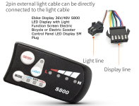
Display: AddMotor branded but I'm about 99% sure it's a Kingmeter SW-LCD
Controller: Lishui LSW 1250
Battery: 48v

What I've tried thus far:
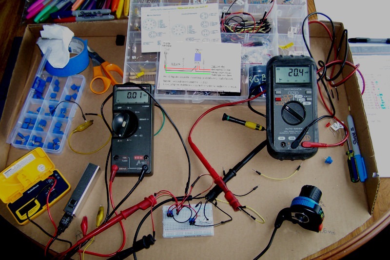
  • Per the manufacturer's troubleshooting guide, I disconnected everything, then connected only the battery and LCD to the controller and turned it on. Same error, so that rules out brakes, throttle, light, and motor.
  • Since the most frequent cause of this error is wiring, I removed the harness from the bike and verified each pin of the LCD connector (display end) has continuity (at least 5 ohms resistance) at the controller end of the cable with no short circuits to other pins.
  • I changed the controller to a newer model, with only the battery and LCD connected and turned it on. Same error, so that sort of rules out the controller unless it just instantly fried a second controller. (as it turns out, that is not a definitive test. In the end it turned out that the display and the original controller were both fried, so getting the same error with the new controller did NOT rule out the original controller also being bad. Note added after resolution.)
  • I didn't have a spare Kingmeter SW-LCD but I did have a spare SW900 so I wired that up. It displayed an Error 10, which is also a communication error a few moments after I powered on the bike. (Not a good test though, not all displays work with all controllers. Note added after resolution.)
  • I reconnected the original LCD and did the reset procedure on it (simultaneously hold up and down buttons) and reset all the settings to what seemed like default settings. No difference, same error 30.
It may be worth mentioning that if I connect the throttle and motor cables, the motor works until the display shuts itself off and kills power to everything.

Any and all guidance/suggestions is greatly appreciated. Thank you in advance.
 
Last edited:
Solution
A Summary of this entire thread, with links to key information when diagnosing an Error 30:

I read through the entire thread and added notes and corrections wherever possible to help prevent misleading anyone trying to diagnose their bike for an Error 30 condition.

Key Post: KT and Lishui wiring sequence diagram, and voltage readings indicating abnormal reading on Yellow (TX) wire.

Next post is also good, it shows both KT, Lishui, and Bafang) configurations. Pay attention to male vs female configurations.

Helpful post if you're working on an Add Motor bike with proprietary harness and controller.

Helpful post if you're working on an Add Motor bike with proprietary harness and controller. Same as...
From left to right.
1. The screen a moment before touching probes together.
2. The screen at the moment the probes touched. (note the small k which only showed for a second)
3. The screen a second or two after the probes touched. (note that the number fluctuated a bit while the probes were touching)
4. The screen a moment after separating the probes. (note the small k which only showed for a second)
5. The screen two to three seconds after separating the probes. (returns to frame 1)
This is how autoranging works (you can temporarily disable it by pressing the Range button once, which sets it to the range it is presently in, pressing again moves to the next range, etc).

Before you touch them it autoranges to the highest range because it's trying to measure a high (infinite) resistance of no connection.

When you touch them it starts autoranging down to the range that best matches the resistance detected, and the screen update is much slower than the actual process, so you only see (usually) one update of the screen as it happens. Sometiems you will see the bar under the numbers move from one side to the other as it scales the reading (like an audio volume level bar in a sound system meter display).

Then it stabilizes, and you get the actual reading. (though I suspect your meter might need calibrating, or a new battery, as 10ohms is pretty high for just the meter leads, especially if they are the original Fluke ones).

When you untouch the leads the process reverses.
 
especially if you own one.

View attachment 339121
From left to right.
1. The screen a moment before touching probes together.
2. The screen at the moment the probes touched. (note the small k which only showed for a second)
3. The screen a second or two after the probes touched. (note that the number fluctuated a bit while the probes were touching)
4. The screen a moment after separating the probes. (note the small k which only showed for a second)
5. The screen two to three seconds after separating the probes. (returns to frame 1)
Wow, what a nice looking "legacy" meter! :) Looks like brand new.

At the risk of dating myself, I too enjoy the ownership of one.

5CyRblJ.jpg


Seen here taking some readings for a throttle thread.... with a lot more wear and tear on it.

though I suspect your meter might need calibrating, or a new battery, as 10ohms is pretty high for just the meter leads, especially if they are the original Fluke ones.
+1

Start with a new 9vdc battery replacement. You can also try a single high quality stranded copper wire to jumper between the two ports on the right just to see if it's the leads.
Mine will read down to .1 ohms as a reference point, with the leads together.


Tommycat Tips on what to do, or NOT what to do with this meter!

Do not test electronic air cleaner circuits that go past 10,000 volts with it.
After getting it refurbished from the Fluke repair shop after doing so, don't try it again! :sick:

Be careful not to go above the rated maximum amperages for each range. Although fused, this is easy to do. Always start with the highest range and then go down if you can. Always replace with the correct size and type of fuse. Anywhere above 10 amps that you might find yourself, use a cheap ammeter with a shunt in the range you're testing.
Do check your continuity for resistance by putting your probes together before testing resistances.
Replace the battery every so often.
Know it's maximum reading values.
Alligator tips are very helpful.

*****Always remember to move your meter leads to the correct ports when going from voltage readings to amperage readings or visa-versa.*****
 
This is how autoranging works (you can temporarily disable it by pressing the Range button once, which sets it to the range it is presently in, pressing again moves to the next range, etc).
This is covered in the manual, but it's funny how it's easier to understand when you say it.
Before you touch them it autoranges to the highest range because it's trying to measure a high (infinite) resistance of no connection.

When you touch them it starts autoranging down to the range that best matches the resistance detected, and the screen update is much slower than the actual process, so you only see (usually) one update of the screen as it happens. Sometiems you will see the bar under the numbers move from one side to the other as it scales the reading (like an audio volume level bar in a sound system meter display).
Ah, I get it now. Thank you
Then it stabilizes, and you get the actual reading. (though I suspect your meter might need calibrating, or a new battery, as 10ohms is pretty high for just the meter leads, especially if they are the original Fluke ones).
I'll put in a new battery, this one has been in there a long time. Hopefully it won't need a calibration.
 
Wow, what a nice looking "legacy" meter! :) Looks like brand new.
Thanks, it stays in it's case when not in use, and I have always been careful with it when I use it.
At the risk of dating myself, I too enjoy the ownership of one.
:D
Start with a new 9vdc battery replacement. You can also try a single high quality stranded copper wire to jumper between the two ports on the right just to see if it's the leads. Mine will read down to .1 ohms as a reference point, with the leads together.
Great tips, I'll definitely start with the new battery, @amberwolf made the same suggestion.
Tommycat Tips on what to do, or NOT what to do with this meter!
Duly noted (entire list).
*****Always remember to move your meter leads to the correct ports when going from voltage readings to amperage readings or visa-versa.*****
I've never tried to read amperage, but after reading the manual and this usage tip, I may do so in the future.
 
@TommyCat and @amberwolf

Meter test:
With a new battery, meter set to auto-range, it now reads only 2 ohms instead of the previous 10 ohms it had with a weak battery. With leads removed and a copper jumper wire across the sockets, meter set to auto-range, it drops all the way down to .02 ohms.

From this test I conclude that my meter is fine, but my leads are not. I'm not sure if they are bad enough to affect other readings such as voltage though.

Pressing the Range button four times fixes the range to either 32k or 320k ohms. Touching the leads together with this setting gives a reading of .02 ohms, which seems likes good setting for testing my harness, so I retested it.

Harness test:
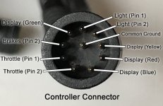
The end result was essentially the same as before except this time I found the broken light wire. I figured the pin hole on the light connector (top end) that seemed to go nowhere and the mystery pin at the controlled connecter (bottom end) had to be a match. So, with a lead connected at each end, I wiggled the (top end) wire around until I get a reading, the break in the wire is right at the ass-end of the light connector, not a tough fix if even desired, I don't think the owner plans to ride at night. Here is the updated labeling of the controller connector.

Harness-pinout-controller-end.jpg
With this second test complete I have concluded the harness is safe to use. If there is desire to use the light, I'll repair the broken end.

Original controller (ghost power) test:
I made a new ghost power tester using a 120v 4 watt bulb to test if the 52 volts on the yellow pin hole of the controller was ghost power or not. The bulb glowed consistently, I left it connected for 10-20 seconds and then tested the voltage again with a meter, it was still at 52 volts. Then I did the bulb test on the red pin hole of the controller, and it also glowed consistently. All the other holes revealed similar voltages to the first time I tested it.

With this second test complete, I have concluded the original controller is NOT safe to use, and I do not plan on trying the jumper to bypass the display.

Factory replacement controller test:
Consistent with the first time I tested this controller, I got extremely low (.02 volts) or no voltage on all holes with the exception of getting 53 volts on the red wire pin hole.
I decided to test the SW900 display with this controller because I had not tested that previously, but I got an Error 10 with it, which I presume is a mismatch of communication protocols between the controller and display.
I would feel safe trying a jumper to bypass the display with this controller, but I can't do that test due to the mismatch of connectors for the motor. I would have to snip the connectors off both controllers and use the connecter from the original on the replacement controller. I'm more inclined to replace the controller and display with a matched set because even if the swapped connector works with a jumper, I'd still be without a display. I searched for an adapter but didn’t have any luck.
 
Last edited:
From this test I conclude that my meter is fine, but my leads are not. I'm not sure if they are bad enough to affect other readings such as voltage though.

I agree on the less than perfect lead(s). You can always keep the 2-ohm offset in your head. But if you plan to use your meter to say, check charger voltage and amperage cut-off setpoints. (Need high accuracy here...) Get new leads... yep, they are expensive. On my fourth pair.


The end result was essentially the same as before except this time I found the broken light wire.

My concern would be if it's not only occasionally contacting to correct wire. But any others in the cable...?


Original controller (ghost power) test:
I made a new ghost power tester using a 120v 4 watt bulb to test if the 52 volts on the yellow pin hole of the controller was ghost power or not. The bulb glowed consistently, I left it connected for 10-20 seconds and then tested the voltage again with a meter, it was still at 52 volts. Then I did the bulb test on the red pin hole of the controller, and it also glowed consistently. All the other holes revealed similar voltages to the first time I tested it.

With this second test complete, I have concluded the original controller is NOT safe to use, and I do not plan on trying the jumper to bypass the display.

Well done! Curious on how you settled on a 4-watt bulb...?


I agree with your logic and parts replacement assessment. (can't splurge for a new upper harness. ;) Looking forward to a positive outcome!
 
I agree on the less than perfect lead(s). You can always keep the 2-ohm offset in your head. But if you plan to use your meter to say, check charger voltage and amperage cut-off setpoints. (Need high accuracy here...) Get new leads... yep, they are expensive. On my fourth pair.
I've had the meter a long time, it will be worth the investment.
Rick: "this time I found the broken light wire."
TommyCat: My concern would be if it's not only occasionally contacting to correct wire. But any others in the cable...?
I suppose that is possible, but the break is at the end of a small cable that only has the two wires in it for the light, and the only time it would be energized if the light were connected and switched on, but it's not even connected for these tests, so I'm thinking it's not what is causing the Error 30.
Rick: "I made a new ghost power tester using a 120v 4 watt bulb.
TommyCat: Well done! Curious on how you settled on a 4-watt bulb...?
It was the only incandescent 120 watt bulb I could find in the box of spare bulbs. Pure happenstance :ROFLMAO: but I like it because it's small.
I agree with your logic and parts replacement assessment. (can't splurge for a new upper harness. ;) Looking forward to a positive outcome!
I contacted the manufacturer, no harness available, no original controller available either, only the replacement I have. The only other part they have is the display, and they want $120 for it 😯

Since this basically boils down to either I have two bad controllers, or one bad display, and this controller seems good, I decided to do the work involved (expose the wires) to test it, which I have done, and will post the results as a separate post in a few minutes.
 
@TommyCat and @amberwolf

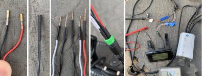
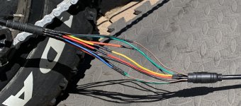
As mentioned, I decided to do the work involved (expose the wires) to test the display, which I have done, but I'm not entirely sure of what the results mean. But first I'll share how I was able to conduct the test on a system that uses entirely waterproof Juliet connectors in case this method (trick) is useful for others. The trick is to make some custom leads...

display-test-leads.jpg
From left to right:
  • For the female ends of the leads I salvaged these tiny female connectors (with wires) from an old computer cable that connected the CD player to the motherboard.
  • Put heat shrink over the ends to ensure they don't short when bunched together in the small male Juliet connector.
  • For the male ends I soldered on solid copper wire from an old analog phone wire, cut to length, added heat shrink to protect from shorts when inserted close together in the small female Juliet connector.
  • A close up of the female ends of the leads in the male connector. Sorry, I didn't take a close up of the male leads in the female connector.
  • Everything hooked up for the test. Remember to mirror your connections!!! Note that I spliced a wire onto the common ground and clipped that onto the voltmeter's negative lead. All of the other leads have a small shaving of wire insulation removed (not next to each other) to expose the wire to touch with the positive lead to get a voltage reading on each wire.
Results: (In the order they were tested. Leads were touching the wires when the switch was powered on. The cycle was repeated for each wire)

Blue 52.5 volts (power lock, kp controller power)
Red 53.3 volts (full battery voltage)
Yellow 1.8 volts (TxD transmission)
Green 4.17 volts (RxD receive)

With an Error 30, I was sort of expecting Yellow or Green to not have voltage, so I'm not sure what this means exactly.
 
TXis probably normal, it shoudl be somewhere around the middle of the 5v range, because it's swithcing rapidly between the two as it sends data. You can't see this on a multimeter, but could on an oscilloscope.

RX will have no valid signal unless it is connected to a controller that is powered on and sending data. If it's unconnected, it's voltage doesn't mean anything as long as it is within the 5v range.

Error 30 just means the display isn't hearing back from the controller. That can be because the display isn't sending, or it isn't turning the controller on, or the controller's LVPS is dead and not powering it's brain, or the brain is pwoered but not sending, or it is sending but not receiving from the display so the display isn't getting the answers to it's questions.

Since you have battery voltage on both B+ and lock / KSI, it means the display is getting and passing thru power to send to the controller and run the controller brain. THe only thing you don't know about it is if it can supply the up to a few hundred mA the controller could draw. (if it can't the voltage will drop as the load increases, while the b+ remains the same). YOu don't want to put much load on that lock pin, because it will blow up the transistor switch in the display at some point.

THe best way to do these tests is with an extension cable between the display and controller, cut into to make a "breakout cable" to access the signals/etc, because it means its' all hooked up just like normal and any loads, etc., will all be normal, so any incorrect signals/voltages in this mode vs separated (like you have tested now) can point you to where an excess load is.
 
THe best way to do these tests is with an extension cable between the display and controller, cut into to make a "breakout cable" to access the signals/etc, because it means its' all hooked up just like normal and any loads, etc., will all be normal, so any incorrect signals/voltages in this mode vs separated (like you have tested now) can point you to where an excess load is.
The only reason I did this test was to see if I could isolate the bad component, but it sounds to me that my test was not definitive in determining that, and even if it was, it would take a component level repair to fix it, which I am not equipped to do anyway.

My neighbor who owns the bike thinks that I have put too much time and effort into this and is prepared to replace the electronics (display, controller, and associated harness/wiring). I don’t feel the same way, I have learned so much and I enjoy working on this stuff, but I do feel that I may have hit my limit on what I will be able to diagnose and repair, and it may be time to face the music and just buy a kit to get the bike back on the road. He has an Amazon gift card and would like to use it to purchase the kit, the only question now is, which one? There’s only a million to choose from!
 
Which kit depends on what features they want, and the job that the system has to do for them (meaning, how much power does that job take, and so how much power the system must provide).

If the bike already did everythign they want, then finding a system that is identical to the existing one in function and voltage/current/power specs is your best bet.

FWIW, if you want to pursue the troubleshooting, then ask what they're going to do with the broken bits. I learned quite a bit about this stuff from other people's broken stuff over the years, and some of it was fixable. :)
 
Which kit depends on what features they want, and the job that the system has to do for them (meaning, how much power does that job take, and so how much power the system must provide).
The owner just wants to get it working again, and he couldn’t care less about bells and whistles. Meaning, he doesn’t care if it has an LCD screen or not, an on/off switch with an LED battery charge level is enough. As for power, he doesn’t want it to perform any different than when it was working, even less power than original would be fine, he doesn’t want to go fast.
If the bike already did everything they want, then finding a system that is identical to the existing one in function and voltage/current/power specs is your best bet.
It already did more than he wants, the LCD was just something it came with, he doesn’t care about a speedometer, odometer, or any of that, so finding a kit with adequate specs (48 volt 10ah battery, 500 watt motor) is the easy part, the hard part is not knowing which are preferred brands, and which to avoid.
FWIW, if you want to pursue the troubleshooting, then ask what they're going to do with the broken bits. I learned quite a bit about this stuff from other people's broken stuff over the years, and some of it was fixable. :)
I’m interested in pursuing troubleshooting, I love learning about this stuff, but I think I may have hit my limit in terms of what to try next. I don’t really understand the difference between a breakout cable and what I did because I can read the signals on each of the wires via the cuts in insulation I made on each wire, but even if I made a breakout cable, I would need a lot of instruction on how to diagnose the signals to find the excessive load, and then more instruction on what to do with that information.

FWIW, he’s not in a hurry to get the bike back, he just feels bad about the time I’m investing, but I assured him I’m not concerned with the time. So, neither of us is in a rush to go out and buy replacement parts, nor is he worried if I destroy anything in the process of trying to fix it, it is mostly a matter of feeling like I hit a dead end and buying replacement parts is the only option.

With that said, I feel fairly confident the factory replacement controller is good, so I’m going to make some custom leads to connect the controller to the motor without cutting off the mismatched connector, and then try the jumper trick at the display connector to bypass the display. If this works, then it pretty much isolates the problem to the display. And at that point I’ll work out a basic on/off switch and battery charge indicator, or, I’ll cut the seal on the display and see if can get lucky repairing it. I’ll post some pictures of my makeshift cable adapter leads in a little while.
 
And at that point I’ll work out a basic on/off switch and battery charge indicator


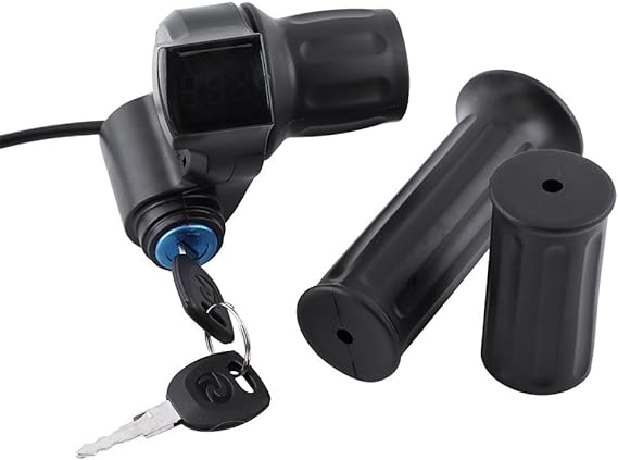
Something like this popped into my head... tons of options along this line. Just a heads up.


51anS4aJeML._AC_SX569_.jpg


As seen here...

Half throttle with key switch and voltage meter.

To pursue the display communication issue a bit farther I would...

Test the TX-RX jumper voltages with battery power to the display, (RED wire),but with the power to the controller (BLUE wire) disconnected.
Then remove the communication jumpers and test the four communication pins individually, noting voltages with just the display wired. And then with display and controller powered.
As mentioned previously, when working properly, the voltage will fluctuate occasionally during communication.
You get a bonus if your prepared to take these readings at the beginning of power-up and looking for this fluctuation.
 
@TommyCat and @amberwolf

SUCCESS, the jumper test (at the display connector) worked!!!!! The replacement controller is good. Everything worked, the throttle worked, the brake cutoffs worked, even the PAS worked, albeit at a default setting, which seemed like max. This was all done as a bench test, not ridden.

Here is the test rig. I didn't take pictures making the leads, but the short of it is, all the bits came from old internal computer connectors.

I can't emphasize enough to future readers that this is for a bench test, you should never ride a bike with this type wiring, it's even a bit sketchy for a bench test.
controller-motor-temp-harness.jpg
I guess now I will cut off the connector I don't have a cable for and permanently attach the one that matches the one on the motor.

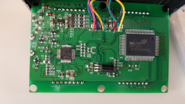
I think one can conclude from this test that the display is bad. I'm going to cut the seal on the display to see if I can open it up and see if I can find anything.
 
Last edited:
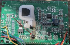
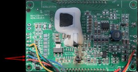
I think I found the problem...

AFAICR that's the transistor the display uses to turn the controller on (it passes battery power from the B+ to the Lock / KSI wire.)

I don't recall the p/n that can be used to fix it, but I know there is a post around here where someone did this, if I can find it. (it probably doesn't matter which display model it is, the circuit is likely the same or very similar for all of them).

But I would bet that you could wire in a non-surface-mount part to make the repair easier. Just depends on whether it's a regular transistor or a fet (probably the former), and whether it's PNP or NPN, or PFET or NFET. (most likely P in both cases, since it switches the actual power positive line)/

This is how they build some versions, this one with an A1013 transistor (barely good for a 48v (13s) battery, according to reports, but whose specs should be good for a lot more, unless it's just too much current (>1A) or heat buildup just gets to it over time).
1694384860560.png


Of course, you can also just jumper the pins at the connector or inside the display or controller if you just turn the system on and off with the battery switch, or put a physical switch in there somewhere if you prefer that. (in either case, the display switch will then only turn the display on and off).
 
Last edited:
Of course, you can also just jumper the pins at the connector or inside the display or controller if you just turn the system on and off with the battery switch, or put a physical switch in there somewhere if you prefer that. (in either case, the display switch will then only turn the display on and off).
I like this idea, the battery has a key and I’m sure the owner will be fine with using it to power up the system. I don’t like the idea of trying to repair a circuit board, on or off the board, but if we can get the display to function for everything other than powering on the system, that would be great. The only question I have is, how exactly do I jumper the pins inside the display, which would be my preference? Do I simply bridge the solder across these two Vias?

jumper-display-circuit-board.jpg
 
The only question I have is, how exactly do I jumper the pins inside the display, which would be my preference? Do I simply bridge the solder across these two Vias?
If those are the B+ and lock, then that would work--the current should be small enough for solder alone to handle this.

Alternately if the PCB hole is large enough to accomodate both wires you could solder the lock wire into the B+ hole along with the B+ wire, twisting the two together prior to insertion.
I did the latter, but I didn't test it yet because I had to disconnect the temp leads to the controller to put the bike away. I'm working on moving the connector from the old controller to the new one, once that is complete it will be easy to test the display.
 
I think I found the problem...


Terrific! Always nice to have a burn-out verified by inspection. (I..E. Autopsy)


What about something like this?
View attachment 339479
As see here.

You know, if you could contact the seller and have him verify that this would work with your controller it would be fantastic.
On some websites that handle this product I've seen mention of a couple different systems...
But as far as communicating properly with your controller (which seems a bit proprietary) would be a shot in the dark IMHO.

If you decide down the road to replace the components, controller and display. I'd recommend a KT product with the controller and display as a set. Get the controller with self-learning ability to help with install. Especially with the proper motor HIGO connector.

Looking forward to what works with the direct display bypass.
 
Terrific! Always nice to have a burn-out verified by inspection. (I..E. Autopsy)
I agree, it absolutely confirms the display was at least part of the problem. I didn’t try the jumper trick on the old controller, so I don’t know if it caused the failure on the display or the other way around, but either way, nice to confirm it was damaged.
You know, if you could contact the seller and have him verify that this would work with your controller it would be fantastic.
On some websites that handle this product I've seen mention of a couple different systems...
But as far as communicating properly with your controller (which seems a bit proprietary) would be a shot in the dark IMHO.
It can’t hurt to ask, but I agree the system seems proprietary.
If you decide down the road to replace the components, controller and display. I'd recommend a KT product with the controller and display as a set. Get the controller with self-learning ability to help with install. Especially with the proper motor HIGO connector.
You didn’t mean KD by chance did you? I have a KD58C display on my daily commuter bike and I really like it, it’s tiny but packed with features.
Looking forward to what works with the direct display bypass.
Unfortunately, it didn’t work. The bike operates as expected without turning on the display, but turning on the display still results in the Error 30. It was a great suggestion by @amberwolf, and well worth the try, but alas that did not pan out.

I talked to the owner, he said he doesn’t care about having a display, he doesn’t care if PAS has only one setting, and he’s fine with using the battery key to turn the bike on and off, so we may decide to permanently bypass having a display at all.

A huge thanks to both of you, the bike is now operable, which is a whole lot better than where we started, and he can always change his mind later about buying a complete kit.
 
Last edited:
Unfortunately, it didn’t work. The bike operates as expected without turning on the display, but turning on the display still results in the Error 30.
Was afraid of that, but hey worth a try. For verification, nothing worked? No speed, battery power, or other usable information displayed?


I talked to the owner, he said he doesn’t care about having a display, he doesn’t care if PAS has only one setting, and he’s fine with using the battery key to turn the bike on and off, so we may decide to permanently bypass having a display at all.
The key would be being stuck in the one level of PAS. I don't know of a work around without a communicating display...
Some systems will stick the controller a certain PAS level with display configuration. Then you can remove and bypass. Some people like a "stealth" mode.
I would encourage you not to leave the display with a toasted component wired into the system. Just use the bypass jumper.

You may want to post your excellent troubleshooting findings and READINGS in a more direct thread post to help other true electron chasers with correct voltage display readings.

Glad to help out. Thanks for taking me along for the ride. :)


Best regards,
T.C.
 
Back
Top