The dreaded Error 30 (communication error) [Resolved]

rick_p

100 W
Joined
Feb 16, 2021
Messages
260
Location
Los Angeles
I'm helping a neighbor diagnose his bike, which displays an Error 30 a few moments after you power on the bike. I found dozens of posts about this particular error across several websites, videos on YouTube, and a troubleshooting guide on the bike manufacturer's website. So, I really didn't think I would need to ask for help here, but I have tried everything I can think of, so I'm seeking suggestions.

Bike: 2018 AddMotor folder with 20" wheels.
Motor: Bafang 500w rear hub motor
Display: AddMotor branded but I'm about 99% sure it's a Kingmeter SW-LCD
Controller: Lishui LSW 1250
Battery: 48v

What I've tried thus far:
  • Per the manufacturer's troubleshooting guide, I disconnected everything, then connected only the battery and LCD to the controller and turned it on. Same error, so that rules out brakes, throttle, light, and motor.
  • Since the most frequent cause of this error is wiring, I removed the harness from the bike and verified each pin of the LCD connector (display end) has continuity (at least 5 ohms resistance) at the controller end of the cable with no short circuits to other pins.
  • I changed the controller to a newer model, with only the battery and LCD connected and turned it on. Same error, so that sort of rules out the controller unless it just instantly fried a second controller. (as it turns out, that is not a definitive test. In the end it turned out that the display and the original controller were both fried, so getting the same error with the new controller did NOT rule out the original controller also being bad. Note added after resolution.)
  • I didn't have a spare Kingmeter SW-LCD but I did have a spare SW900 so I wired that up. It displayed an Error 10, which is also a communication error a few moments after I powered on the bike. (Not a good test though, not all displays work with all controllers. Note added after resolution.)
  • I reconnected the original LCD and did the reset procedure on it (simultaneously hold up and down buttons) and reset all the settings to what seemed like default settings. No difference, same error 30.
It may be worth mentioning that if I connect the throttle and motor cables, the motor works until the display shuts itself off and kills power to everything.

Any and all guidance/suggestions is greatly appreciated. Thank you in advance.
 
Last edited:
Solution
A Summary of this entire thread, with links to key information when diagnosing an Error 30:

I read through the entire thread and added notes and corrections wherever possible to help prevent misleading anyone trying to diagnose their bike for an Error 30 condition.

Key Post: KT and Lishui wiring sequence diagram, and voltage readings indicating abnormal reading on Yellow (TX) wire.

Next post is also good, it shows both KT, Lishui, and Bafang) configurations. Pay attention to male vs female configurations.

Helpful post if you're working on an Add Motor bike with proprietary harness and controller.

Helpful post if you're working on an Add Motor bike with proprietary harness and controller. Same as...
Strangely, I got an email saying there was a response, but I don’t see it here on the thread. The responder asked “Is it diy or did you buy it. Displays and controllers come as matched pairs.”

And the answer is, it’s a factory bike with all the original (matched) parts. Even the second controller we tried was a factory replacement, but they did say that they no longer had the same controller the bike originally shipped with and sent an updated model. The bike ran fine for years before the error started. It wasn’t ridden a lot, but it never sat for long periods of time either.
 
It may be worth mentioning that if I connect the throttle and motor cables, the motor works until the display shuts itself off and kills power to everything.
When does it shut off? (does ti happen after a specifc amount of time everyt ime, or under specific conditions, etc?)

Is this different from the error 30 issue, or is taht what you mean by shut off?

(shut off usually means actually turn off, blank display, no lights, no power, etc).


FWIW, error 30 is a comm errror, which can mean a broken wire or poor connection anywhere from inside controlelr up to inside dsiplay (even thouhg the harness itself tested ok, presumably that harness is just what plugs into the controller and the display--has the connection to inside them on the actual pcbs been tested?. could even be a failed comm buffer chip in the km display.

if it's an actual comm fault where no data is being sent by one oro the other, youc an measure the voltage on the tx and rx lines relative to ground with the display and controller connected together, if you can access those pins, and if there's stuff oging oin you'll see about 2.5v on the line. if it's a steady 0v or 5v, no data is being sent on the line, so if it's tx from the dipslay that means the display isn't sending anything to the controller for whateer reason. the controller si probably sending ot the display because you are getting same problem wtih two contorller.s

the diffferent error you get with the sw900 is probably because the protocol or data being sent back and forth is different betweent eh controller and didsplay s othey can't udnerstand eacy other.
 
When does it shut off? (does ti happen after a specific amount of time every time, or under specific conditions, etc?)
A specific amount of time, every time.
Is this different from the error 30 issue, or is that what you mean by shut off?
Not different, that is what I meant by shut off. What it does exactly is, it turns on and everything looks normal for a few seconds, and if I twist the throttle within those few seconds the motor runs, then the error 30 comes on the screen and blinks for a few seconds, and the motor is still running during that time, and then the screen goes blank (it turns itself off), and of course the motor stops.
(shut off usually means actually turn off, blank display, no lights, no power, etc).
Exactly
FWIW, error 30 is a comm errror, which can mean a broken wire or poor connection anywhere from inside controller up to inside display (even though the harness itself tested ok, presumably that harness is just what plugs into the controller and the display--has the connection to inside them on the actual pcbs been tested?. could even be a failed comm buffer chip in the km display.
It did cross my mind that just because the wire I'm sticking in the female end of the tiny Juliet connector to test the harness makes a connection, doesn't mean the tiny pins of the male Juliet connector make a connection when they go together, but that seemed unlikely. I opened the controller to check the data wires connected to the PCB securely, and had resistance to the pins, and those looked ok, and I didn't see any other signs of failure. The display is sealed shut, so there was no way to check anything at that end.
If it's an actual comm fault where no data is being sent by one or the other, you an measure the voltage on the tx and rx lines relative to ground with the display and controller connected together, if you can access those pins, and if there's stuff going on you'll see about 2.5v on the line. if it's a steady 0v or 5v, no data is being sent on the line, so if it's tx from the display that means the display isn't sending anything to the controller for whatever reason. The controller is probably sending to the display because you are getting same problem with two controllers.
Accessing those pins would require removing some sheathing to stab the wires with a pin or something, all very tricky at best. I agree that between the controller and the display, if one is bad it's more likely to be the display because the same error is happening with two different controllers, and one is new. And as you point out below, I haven't ruled out the display properly yet.
The different error you get with the sw900 is probably because the protocol or data being sent back and forth is different between the controller and the display, they can't understand each other.
I wondered about that. I assumed at the time that the two displays simply used a different error code number to report the same problem, but given you said there's a good chance there's an incompatibility between the controller and the SW900, now I'm thinking there's a good chance the problem is in the display, and it's the one thing at this point I haven't truly ruled out as the possible fault. I'll call the manufacturer of the bike and see if I can order a replacement, if not, I'm pretty sure I can find the same one online that just isn't branded with their name on it (I'm about 99% sure it's a Kingmeter SW-LCD).
 
A quick update. I reached out to the bike manufacturer (AddMotor) and sent them all the information I posted here, the first reply I got they asked me a bunch of questions that had nothing to do with the problem, they were trying to determine if the bike was under warranty. I replied with all the information including the serial number and on the second reply I got, they sent me the troubleshooting guide that I had already sent them the results of in my first email 🤦‍♂️.

In the meantime I searched online for a King-meter SW LCD and they are available, but not at any of the places I have done business, so I’m waiting to see what the manufacturer says and see if they have a replacement and what it costs. I’m also considering purchasing a whole new kit (matching controller, display, LCD, wiring harness) and would like a recommendation for that.
 
"It may be worth mentioning that if I connect the throttle and motor cables, the motor works until the display shuts itself off and kills power to everything."

Good. That means your controller will power up with a default PAS and throttle if the display is not working, Many of them do that.

Displays and controllers are somewhat stand alone units. A display only needs power and ground to power up. Yoir controller only needs power/ground plus one input raised to battery voltage to power up. As you have found out, since the connectors are the same, you can connect incompatible displays and they power up..

Here is a pinout for the flat JST connector on my KT LCD3 dispaly, I have a Brainpower S866 and an SW900 that use the identical pinput. When the display powers up, it raises the IGN lead to the battery level, which starts the controller. If the serial data leads work, it then sets up your start levels for PAS/throttle. If not, the controller uses its default levels. As soon as the display realizes there is a comm error, it lowers the voltage on the blue wire and the controller shuts off. I hope this explanation helps you understand what's going on. . Anyway, you could run your bike with a jumper until you sort out the display issue. With a jumper, the controller stays on.

KT-Jumper.jpg


One caution. There are SW900 displays and there are SW900 displays. The firmware may be different on them. We had a Kingmeter representative post a welcome post here once. Sent him a pic of my SW900 display with a query about how it measures the speed, and he said it used non Kingmeter firmware.
 
I'm having the same problem with mine. Lishui controller. With a bafang 750w motor and a kd21c display it turns on and after 10 seconds it starts flashing a error 30 code. It will run for about 30 seconds and then it shuts off. I can turn it back on and continue for Another 30 seconds before it does it again. But it also affects my pedal assist..... that is running at full power until it shuts off. I have changed out most of the parts from my other bike and no difference. But all the parts from this one work fine on my other one.......I put a new wire harness in it and still have the same problem. I'm going to put a new controller in it tomorrow and hopefully it will fix the problem. It's the last price left to replace lol. I will let you know what the results are
 
What do you like about that setup that you stick with it no matter what when it doesnt work and throw money at it. Just ride without all that extra junk, its the junk that can go wrong. Probably just a loose pin in a connector from their cheapness or wrong controller because it wasnt purchased as a combo set, which in itself is not a guarunteed success when buying from sellers of different stripes. I had a cheap connector pin loose, the whole controller would reset itself over certain bumps, and that took a delay of 4 seconds so I had to adapt. Now I just snip all that cheap junk off and slap on 4mm barrel connectors or 5.5mm or the big beasts 7 or 8mm, and XT90's because they big, XT60's just a bit to small, Andersons are mechanically attached and thats not my cup of Earls Grey tea. Proper brand name Molex I have used, but they are to small and cumbersome for bigger fingers.
 
Last edited:
First and foremost, thank you for the amazing post, this may answer something I wondered... if it was possible to bypass the display.
Now, when you say...
Anyway, you could run your bike with a jumper until you sort out the display issue. With a jumper, the controller stays on.

View attachment 338018
Are you saying to disconnect the display and add the jumpers to the connector on the side that is coming from the controller? (the answer to this question turned out to be yes, this message added after resolution)

If so, the connector coming from my controller is the water-proof Juliet style, but I found a diagram that is for KT and Lishui controllers. BEWARE that other displays (Bafang for example) and controllers have different configurations, it's very important to check your voltages and verify your configuration before connecting a new display and turning on your bike.

display-pinout.jpg
 
Last edited:
I have changed out most of the parts from my other bike and no difference. But all the parts from this one work fine on my other one.
Are the two bikes identical models? When you said "you changed out most of the parts" did that include the controller, display, and harness?

Same question for this statement "all the parts from this one work fine on my other one." Did that include the controller, display, and harness? If so, that only leaves the battery as a possible sources of the problem if the motor was disconnected.
I put a new wire harness in it and still have the same problem. I'm going to put a new controller in it tomorrow and hopefully it will fix the problem. It's the last price left to replace lol. I will let you know what the results are
I can't wait to hear what the out come is.
 
What do you like about that setup that you stick with it no matter what when it doesnt work and throw money at it. Just ride without all that extra junk, its the junk that can go wrong. Probably just a loose pin in a connector from their cheapness or wrong controller because it wasnt purchased as a combo set, which in itself is not a guarunteed success when buying from sellers of different stripes. I had a cheap connector pin loose, the whole controller would reset itself over certain bumps, and that took a delay of 4 seconds so I had to adapt. Now I just snip all that cheap junk off and slap on 4mm barrel connectors or 5.5mm or the big beasts 7 or 8mm, and XT90's because they big, XT60's just a bit to small, Andersons are mechanically attached and thats not my cup of Earls Grey tea. Proper brand name Molex I have used, but they are to small and cumbersome for bigger fingers.
You're right, but to do that means replacing all the fancy (bells and whistles) junk with with new, basic models of the minimum required components, which isn't exactly cheap either. So, either way you're spending a chunk of change to get up and running again. Granted, the one added benefit of stripping it down to the basics is it will likely work on the first try, and you will have less headaches down the road, but did I mention I like bells and whistles? ;)
 
Are the two bikes identical models? When you said "you changed out most of the parts" did that include the controller, display, and harness?

Same question for this statement "all the parts from this one work fine on my other one." Did that include the controller, display, and harness? If so, that only leaves the battery as a possible sources of the problem if the motor was disconnected.

I can't wait to hear what the out come is.
Yes they are identical bikes. I put the new controller in it today and the problem is solved. I will have to reprogram the display to get the pedal assist working properly I'm glad that I had a same bike to pinpoint the problem because I heard so many different opinions and ideas. And you tube was not any better lol
 
Yes they are identical bikes. I put the new controller in it today and the problem is solved. I will have to reprogram the display to get the pedal assist working properly I'm glad that I had a same bike to pinpoint the problem because I heard so many different opinions and ideas. And you tube was not any better lol
That is fantastic news, I’m really glad the controller fixed your problem. I tried a similar but not exact replacement controller that came from the bike manufacturer, who said the replacement is just an upgraded version of the original, but I got the same error from it as well, so I’m not sure if the controller is the problem in my case.
 
There was a series of Lishui controllers with weak level shifting transistors. @Agressor110 described how to solve this problem in the German forum.
But SMD soldering skills are necessary for the fix.

regards
stancecoke
I translated the text, he doesn’t give all the details for the repair in the post, but he does say you can contact him for the details. I’m not sure if I want to go that route but I might try step 1 where you test if the display sends a signal to the controller. Here is the pertinent text for those who are interested in what he said.

Good day everyone,
I had exactly the same phenomenon on two Lishui controllers.
After opening the controllers and removing this penetrating sealing compound, I unfortunately could not detect a defect in a component.
I then contacted the forum member "Hochsitzcola".
However, electronics and SMD soldering skills are already a prerequisite!
He then supported me step by step in limiting errors.
Error 30 means communication error between display and controller....
So with a level converter and laptop, log the signals between the display and the controller.
1. Does the display send?
If not, try another display.
Display sends but controller still makes mistakes 30>
2. Does the output of the CPU on the controller board send a plausible signal but does not arrive at the Green RX connection cable on the controller?
Then there is a chance that two overvoltage-sensitive transistors between the CPU and the board connection are defective.
3. Encode, order and solder imprint of the suspicious transistor (ESD compliant)
4. Test controllers - and lo and behold - everything works again, since the error on two controllers (from Fischer Bike ETD/h 1806) was apparently not an isolated case and conceivable with similar controllers from Lishui.
5. Pour the board again - Done.
If you have any detailed questions, please contact me.
Thank you again for the great support at Hochsitzcola.
 
I heard back from AddMotor, they want $120 for a new display. That seems a bit steep to me, especially when I can buy a matched kit and replace the display, controller, and harness for not much more. I’m still deciding what to do.
 
he doesn’t give all the details for the repair in the post
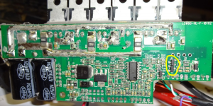
Lishui has several different board layouts for the same schematic. You will find two transistors somewhere on your board labeled with Q1 and Q3. These are the suspicious components ;)

regards
stancecoke

Example:

1692198484522.png
 
Lishui has several different board layouts for the same schematic. You will find two transistors somewhere on your board labeled with Q1 and Q3. These are the suspicious components ;)

regards
stancecoke
I looked inside the controller and was unable to locate those transistors, but to be honest I didn’t try that hard either because I don’t think the controller is the problem, and I don’t have the parts to replace the transistors with anyway. The real reason for opening the controller was to see if I could locate which cable pins were the which color wires so I could use the jumper wires to bypass the display, which is what I suspect is the problem. Unfortunately, that didn’t pan out either because even though I could see the wires, trying to use ohms resistance on the pins didn’t really work, I got readings from almost all the pins, so that was unfruitful. (In the end, the display was fried, and the controller may have been damaged in the process. Note added after resolution.)
 
Last edited:
Anyway, you could run your bike with a jumper until you sort out the display issue. With a jumper, the controller stays on.
Unfortunately, I was unable to determine which pins to use the jumper on with the Juliet connector. I tried opening the controller to figure out the wire colors using ohms resistance at the pins, but that didn’t work because I was getting readings on all the pins from the wires inside the controller.
One caution. There are SW900 displays and there are SW900 displays. The firmware may be different on them. We had a Kingmeter representative post a welcome post here once. Sent him a pic of my SW900 display with a query about how it measures the speed, and he said it used non Kingmeter firmware.
I have a SW900 display that has the same connector as the one in your picture, and I’d gladly buy a new controller that is compatible with it if I knew which ones are compatible with it. Any suggestions?
 
Last edited:
I was unable to determine which pins to use the jumper on with the Juliet connector
You have to connect the blue wire to the red wire on the display cable to switch on the controller without display.
if I knew which ones are compatible with it
The 5s protocol has the option to use an encrypted handshake between the display and the controller at startup. Some OEMs use this option, some do not.
If your display expects the the right key from the controller to switch to normal working mode, you will need an original spare part from the OEM.

regards
stancecoke
 
You have to connect the blue wire to the red wire on the display cable to switch on the controller without display.
I guess I didn’t explain the situation very well, I can’t see the wires so I don’t know which holes are the red and blue wires in the waterproof Juliet connector. I posted a picture on Tuesday (scroll up) that I found on the web that supposedly shows which holes are which color, but I don’t know if I can trust that, I don’t know if my display follows the “standard.” Opening the controller to trace the wires didn’t work, l got resistance readings in more than one hole.

What I’m going to try this morning is, I’m going to connect the controller and harness, turn the key on the battery to the on position and take voltage readings in each hole of the connector to see if I can determine if mine follows ”the standard.” If so, then I will feel safe using the jumper trick.

The 5s protocol has the option to use an encrypted handshake between the display and the controller at startup. Some OEMs use this option, some do not.
If your display expects the the right key from the controller to switch to normal working mode, you will need an original spare part from the OEM.
I don’t know the origin of the SW900 I have, it’s not the one off the bike in question, it is a spare that was given to me by a friend, I’m fairly certain he bought it online as a standalone item, I will ask him, but to your point, there is still no telling whether it expects the 5s protocol or not.
 
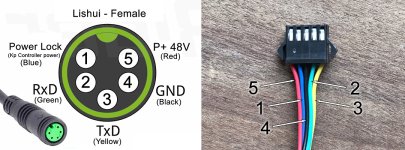
pinout-lishui.jpg

The image on the left above is an updated version of the image posted by @stancecoke below, I converted it to the female version of the connector because that is what mine has. Note that this configuration is for Lishui controllers and associated displays. The connector on the right is from an SW900 and I do not know what controller it fits but I "think" this is the standard wiring configuration for most controllers that use this style connector.

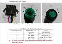
The table below and the numbers I applied to the picture of my connector also come from the image I posted earlier in this thread. The image was found on the web, it is not specific to my display, but is supposed to be "the standard." I recreated the table below in real text so search engines can pick it up, but readers beware that this may not be correct, read the findings below the chart before following this.

Table: Wire sequence for KT and Lishui controllers
KT and Lishui wiring sequenceWire colorFeature it provides
1Blue (Kp)Controller power line (aka power lock)
2Green (RX)Display data receiving line
3Yellow (TX)Display data transmission line
4Black (Ground)Display ground line
5Red (Power - VCC)Display power line (full battery power)

I connected the controller and main harness, turned the battery on, and then take voltage readings in each hole of the connector to see if I could determine if my controller and harness follows ”the standard.”

Here are the readings I got...
Pin 1 - .84 volts (blue?)
Pin 2 - .75 volts (green?)
Pin 3 - 52.3 volts (yellow?)
Pin 4 - I assumed this pin was ground based on the information above and kept my negative probe connected here.
Pin 5 - 53.2 volts (red?)

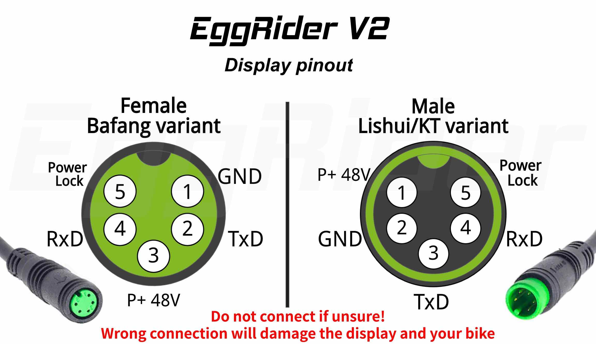
What I don't understand is why is there near full battery voltage on pin 3, which is supposed to be yellow (TX) according to the EggRider diagram.

Note that the image from EggRider conflicts with the image below that @docw009 posted earlier. His image indicates that the green and yellow wires are inverse to this diagram. In his image the green wire is labeled TX and the yellow wire is labeled RX, and in this image they are inverse of that, the green wire is labeled RX and the yellow wire is labeled TX. And as you can see in the readings I got from my controller, pin 3 (possibly yellow) had nearly full battery level voltage on it, so it seems to me that if I had followed the instructions on the other diagram to put a jumper between pin holes 4 (ground) and 3 (yellow), it would have caused fireworks when I turned the battery on. Note that there's a good chance there should not be near full battery power on the yellow wire, so I may have a problem here.

docw009_KT-Jumper.jpg

A side note to all this is, in other posts I found about bypassing the display don't mention adding any other jumpers other than the one from red to blue (battery to controller power), so I'm not sure what a jumper from black to yellow (ground to RX) is supposed to accomplish anyway.

Unfortunately, I'm not feeling very confident in my findings, I'm not comfortable with assuming pin 5 is battery power and pin 1 is blue and provides power to the controller. I'll wait to see what others think.
 
Last edited:
The Eggrider Homepage provides this drawing:
eggrider_v2_display_pinout.jpeg

So connect pin 1 to pin 5!

You can easily find the GND pin, it has 0 ohms to battery -

regards
stancecoke
 
Last edited:
So connect pin 1 to pin 5!

You can easily find the GND pin, it has 0 ohms to battery -
Thanks so much for posting the picture, it explains a lot, and I feel confident about trying the bypass. I updated the diagram in my previous post to be consistent with this one, I made mine the female version of the pinout because mine is female, but now there are both male and female versions to make them easier to read for others in the future. A quick question...

If the bypass works, does that prove that the display is bad, or could the controller still have a problem with communicating with any display?
 
Last edited:
Hi rick_p,

I'd still feel a bit uneasy with full battery power apparently on two pins, when it should only be on one. (Display disconnected right?)
Wouldn't you want to get to the bottom of this first? Perhaps you have a bad harness cable... Are they ghost voltages?
Find the true ground pin hole, or use battery negative for retesting the pin hole voltages...

Regards,
T.C.
 
Back
Top