TSDZ2 EBike wireless standard (like Specialized Turbo Levo) - OpenSource

beemac said:
rananna said:
@beemac, I implement this by simply turning on the red led when the brake pin is active and turning it off when released.
I have a 5 second timer that will turn it off also.
I just used bsp_board_led_on(LED_R__PIN); to turn it on, which is why it is too bright.
I tried to use a pwm sequence without ant delay that simply turned on the led, but I could not get it to turn off.
It is probably user error on my part, but could you please tell me how to use the pwm sequencer to accomplish this?
Perhaps we need a couple of functions addedd like function pwm_led_on and pwm_led_off?

Why is having the LED on solid red better than it blinking? If you really want a solid red - then just create a led sequence - LED_RED, WAIT(5000), END_SEQUENCE, END_SEQUENCE - then if you want to turn it off early - just call play_now with the LED_OFF sequence and 0 delay...

And I still think we should let people decide if the down assist yellow is mixed yellow (like i see) or separate red+green as it's useful to be able to see what you're pressing in the dark. @Casainho I think you have super vision if you see discrete leds not mixing! :)
Ok thanks!
 
beemac said:
[ @Casainho I think you have super vision if you see discrete leds not mixing! :)

One thing that occurs to me is that, in addition to mixing looking different at different pwm intensity levels, we are powering the controller board with 5v while the remote board is powered by 3v.
That might have an effect on led current and hence mixing perception as well.
I will check this out , but I can't do that today. I will certainly look at it tomorrow.
 
rananna said:
beemac said:
[ @Casainho I think you have super vision if you see discrete leds not mixing! :)

One thing that occurs to me is that, in addition to mixing looking different at different pwm intensity levels, we are powering the controller board with 5v while the remote board is powered by 3v.
That might have an effect on led current and hence mixing perception as well.
I will check this out , but I can't do that today. I will certainly look at it tomorrow.

Ah maybe - to me it's a really good yellow but yes I'm 5v all the way. I will make a remote soon I promise - just so much else going on...not had as much time as i did a few weeks ago
 
rananna said:
beemac said:
rananna said:
@beemac, I implement this by simply turning on the red led when the brake pin is active and turning it off when released.
I have a 5 second timer that will turn it off also.
I just used bsp_board_led_on(LED_R__PIN); to turn it on, which is why it is too bright.
I tried to use a pwm sequence without ant delay that simply turned on the led, but I could not get it to turn off.
It is probably user error on my part, but could you please tell me how to use the pwm sequencer to accomplish this?
Perhaps we need a couple of functions addedd like function pwm_led_on and pwm_led_off?

Why is having the LED on solid red better than it blinking? If you really want a solid red - then just create a led sequence - LED_RED, WAIT(5000), END_SEQUENCE, END_SEQUENCE - then if you want to turn it off early - just call play_now with the LED_OFF sequence and 0 delay...

And I still think we should let people decide if the down assist yellow is mixed yellow (like i see) or separate red+green as it's useful to be able to see what you're pressing in the dark. @Casainho I think you have super vision if you see discrete leds not mixing! :)
Ok thanks!

Edited my post as you replied - make sure you add a led off to the 5s red sequence:

LED_RED, WAIT(5000), LED_OFF, WAIT(0), END_SEQUENCE, END_SEQUENCE

then play now a sequence like (think there already is one) if you want to cancel early

LED_OFF, WAIT(0), END_SEQUENCE, END_SEQUENCE
 
Tiger_one said:
@casainho
It is an M2 .79 pitch plastic thread forming screw pan head phillips. Still looking for purchase link. Most are 100 pieces.

Something like these, but you may need longer.https://www.ebay.com/itm/Black-Zinc-Phillips-Pan-Head-Thread-Cutting-Self-Tapping-Screw-M1-4-M1-7-M2-M2-3/153446637938
Thanks!! meanwhile I adapted the design for M2x12 wood screws that I bought locally but did file up to 12mm. The link you shared has M2x12, so that is great!! -- I just bought them and I saw there are many sellers selling them, so it is good for the project to have many potential sources.

The current design uses:
- 4x M2x12
- 1x M2x original screw
- 1x M2x original screw for the buttons PCB


@rananna, I want to ride and I wanted to configure the remote to control my Garmin Edge but then by my mistake It did enter in bootloader mode and after I flashed it worked a bit but then it stooped to work at all, no LED reaction to buttons - maybe the battery is empty?? - I will check tomorrow and meanwhile I will probably assembly my new remote with the printed parts...
 
casainho said:
Tiger_one said:
@casainho
It is an M2 .79 pitch plastic thread forming screw pan head phillips. Still looking for purchase link. Most are 100 pieces.

Something like these, but you may need longer.https://www.ebay.com/itm/Black-Zinc-Phillips-Pan-Head-Thread-Cutting-Self-Tapping-Screw-M1-4-M1-7-M2-M2-3/153446637938
Thanks!! meanwhile I adapted the design for M2x12 wood screws that I bought locally but did file up to 12mm. The link you shared has M2x12, so that is great!! -- I just bought them and I saw there are many sellers selling them, so it is good for the project to have many potential sources.

The current design uses:
- 4x M2x12
- 1x M2x original screw
- 1x M2x original screw for the buttons PCB


@rananna, I want to ride and I wanted to configure the remote to control my Garmin Edge but then by my mistake It did enter in bootloader mode and after I flashed it worked a bit but then it stooped to work at all, no LED reaction to buttons - maybe the battery is empty?? - I will check tomorrow and meanwhile I will probably assembly my new remote with the printed parts...
Sounds like you were in configuration mode. Just follow the instructions in the documentation to enable the garmin.
I have checked this many times and it works well.
Even so, it should give you some indication by led. Try a new battery.
 
Printing today, still steep learning curve even just slicing. PETG is tough and sorta hard to print, but starting to get it I think. Switched from .4 head to .6, which made it somewhat easier. 250c print head and 70c bed.

Still a little rough but close, great job on the design casainho!

20210302_215107.jpg20210302_215118.jpg
 
Tiger_one said:
Printing today, still steep learning curve even just slicing. PETG is tough and sorta hard to print, but starting to get it I think. Switched from .4 head to .6, which made it somewhat easier. 250c print head and 70c bed.

Still a little rough but close, great job on the design casainho!

20210302_215107.jpg20210302_215118.jpg
Thanks for sharing!! And I hope you have PLA, wich is cheaper, easier to print and buy. PLA is more than enough for the remote case!!

Maybe I will finish today or in 3 days the remote. You should try to print with PLA and 0.1mm layer for the best quality. Currently for testing I am printing only with 0.28mm.
 
rananna said:
Sounds like you were in configuration mode. Just follow the instructions in the documentation to enable the garmin.
I have checked this many times and it works well.
Even so, it should give you some indication by led. Try a new battery.
As I will need to disassembly my current remote to check the battery as also I am assembling the new ones, that will take some time - can we move forward to release the new stable version? is that ok for you guys?


Here the way I am using thin wires and double-sided adhesive tape to fix the battery, wires and the board. The tape also electrically isolates the battery face from the bottom of the NRF52 board.

I also added a 4mm hole, as seen near the battery, to pass the brake sensor cable:


casainho said:
As I will need to disassembly my current remote to check the battery as also I am assembling the new ones, that will take some time - can we move forward to release the new stable version? is that ok for you guys?

Before releasing, I would like to update the documentation, fix the brake intensity, and remove the flash when powering on.
I will try to give you a PR for these today.
 
casainho said:
Thanks for sharing!! And I hope you have PLA, wich is cheaper, easier to print and buy. PLA is more than enough for the remote case!!

Maybe I will finish today or in 3 days the remote. You should try to print with PLA and 0.1mm layer for the best quality. Currently for testing I am printing only with 0.28mm.

I do have PLA, thanks for the printing tips. I will save the PETG for tough outdoors or in the car stuff.
Do you use a release? I am on Ender 5 Pro with magnetic base, which is fine for PLA, but about to wear it out removing the PETG.
 
rananna said:
casainho said:
As I will need to disassembly my current remote to check the battery as also I am assembling the new ones, that will take some time - can we move forward to release the new stable version? is that ok for you guys?

Before releasing, I would like to update the documentation, fix the brake intensity, and remove the flash when powering on.
I will try to give you a PR for these today.

Done.
PR added for both docs and code.
I didn't touch @beemac's code for remote signalling.
At the present time it is not in agreement with the wireless remote.
 
rananna said:
beemac said:
[ @Casainho I think you have super vision if you see discrete leds not mixing! :)

One thing that occurs to me is that, in addition to mixing looking different at different pwm intensity levels, we are powering the controller board with 5v while the remote board is powered by 3v.
That might have an effect on led current and hence mixing perception as well.
I will check this out , but I can't do that today. I will certainly look at it tomorrow.

@beemac, @casainho,
I compared the wireless remote color mixing on the board controller to the wireless remote
Mixing is definitely inferior at 3V than it is at 5V, probably due to the lower current
Also the perception of color mixing is definitely affected by light intensity.
Higher intensity=better color mixing.
 
rananna said:
@beemac, @casainho,
I compared the wireless remote color mixing on the board controller to the wireless remote
Mixing is definitely inferior at 3V than it is at 5V, probably due to the lower current
Also the perception of color mixing is definitely affected by light intensity.
Higher intensity=better color mixing.
Visually I think is important to not have much light, since the light is against our eyes and kind of blocks the light around us we should see - on the 860C display I have the need to put the brightness at min value at night and probably I would go even lower if possible. On the display we can switch between day / night but for simplicity I think we should use only a brightness value on the remote and so choose a lower value as possible. Maybe future versions can have a configuration for brightness value.

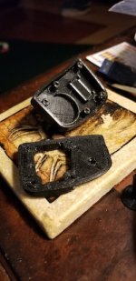
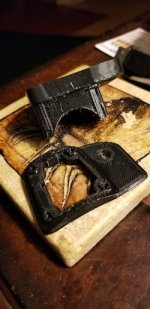
I 3D printed new parts with 0.2mm layer so I could have a better quality parts. I could go to 0.1mm layer but that would take to much time and I was in a hurry.

I blocked the brake wire with a small zip tie, so it will be hard to pull it to much up to damage:


It is hard to see but the battery thin wires are soldered - the power pins on the board are just on the direction of the green power wires. The brake wires were placed under the board so they are not visible.


Done!! Added a bit of transparent silicone on the LED hole. Later I want to put the same silicone between this 2 3D printed parts and on the hole of the brake wire, that way I will have a water prof wireless remote :)
 
casainho said:
Visually I think is important to not have much light, since the light is against our eyes and kind of blocks the light around us we should see - on the 860C display I have the need to put the brightness at min value at night and probably I would go even lower if possible. On the display we can switch between day / night but for simplicity I think we should use only a brightness value on the remote and so choose a lower value as possible. Maybe future versions can have a configuration for brightness value.
Actually, I have already implemented a three level brightness control on the wireless remote in the current release candidate.
from https://opensourceebike.github.io/operation.html:
Double click on the ENTER button to set one of 3 levels for LED intensity. Every double click will set a new LED intensity. The RED, GREEN, and BLUE LEDs will long flash followed by a short flash of either RED or GREEN (depending on whether a garmin is connected) so the effect of the new setting can clearly be seen.
 
casainho said:
rananna said:
@beemac, @casainho,
I compared the wireless remote color mixing on the board controller to the wireless remote
Mixing is definitely inferior at 3V than it is at 5V, probably due to the lower current
Also the perception of color mixing is definitely affected by light intensity.
Higher intensity=better color mixing.
Visually I think is important to not have much light, since the light is against our eyes and kind of blocks the light around us we should see - on the 860C display I have the need to put the brightness at min value at night and probably I would go even lower if possible. On the display we can switch between day / night but for simplicity I think we should use only a brightness value on the remote and so choose a lower value as possible. Maybe future versions can have a configuration for brightness value.

I 3D printed new parts with 0.2mm layer so I could have a better quality parts. I could go to 0.1mm layer but that would take to much time and I was in a hurry.

I blocked the brake wire with a small zip tie, so it will be hard to pull it to much up to damage:


It is hard to see but the battery thin wires are soldered - the power pins on the board are just on the direction of the green power wires. The brake wires were placed under the board so they are not visible.


Done!! Added a bit of transparent silicone on the LED hole. Later I want to put the same silicone between this 2 3D printed parts and on the hole of the brake wire, that way I will have a water prof wireless remote :)
This looks really good!
I can really appreciate the enormous amount of time and effort needed to get to this stage on the 3d design.
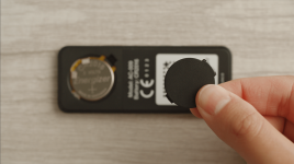
the only comment I have on the design, and please take this as constructive criticism, is that replacing the battery involves quite a bit of surgery. It is not easily done on the road if the battery needs replacement.
It would be nice if the design has some kind of removable access port for the cr2032 like:cover.png
 
casainho said:
rananna said:
@beemac, @casainho,
I compared the wireless remote color mixing on the board controller to the wireless remote
Mixing is definitely inferior at 3V than it is at 5V, probably due to the lower current
Also the perception of color mixing is definitely affected by light intensity.
Higher intensity=better color mixing.
Visually I think is important to not have much light, since the light is against our eyes and kind of blocks the light around us we should see - on the 860C display I have the need to put the brightness at min value at night and probably I would go even lower if possible. On the display we can switch between day / night but for simplicity I think we should use only a brightness value on the remote and so choose a lower value as possible. Maybe future versions can have a configuration for brightness value.

I 3D printed new parts with 0.2mm layer so I could have a better quality parts. I could go to 0.1mm layer but that would take to much time and I was in a hurry.

I blocked the brake wire with a small zip tie, so it will be hard to pull it to much up to damage:


It is hard to see but the battery thin wires are soldered - the power pins on the board are just on the direction of the green power wires. The brake wires were placed under the board so they are not visible.


Done!! Added a bit of transparent silicone on the LED hole. Later I want to put the same silicone between this 2 3D printed parts and on the hole of the brake wire, that way I will have a water prof wireless remote :)

Looks really good, nice work!
 
rananna said:
rananna said:
beemac said:
[ @Casainho I think you have super vision if you see discrete leds not mixing! :)

One thing that occurs to me is that, in addition to mixing looking different at different pwm intensity levels, we are powering the controller board with 5v while the remote board is powered by 3v.
That might have an effect on led current and hence mixing perception as well.
I will check this out , but I can't do that today. I will certainly look at it tomorrow.

@beemac, @casainho,
I compared the wireless remote color mixing on the board controller to the wireless remote
Mixing is definitely inferior at 3V than it is at 5V, probably due to the lower current
Also the perception of color mixing is definitely affected by light intensity.
Higher intensity=better color mixing.

Mmm... interesting... Maybe for a future release I'll change the mix levels for different voltages. It makes sense thinking about it - because I lower the green intensity 50% compared to red - and it's not a linear response - then at 3.3v green may well be much dimmer than red. Whereas at 5v they mix well because they are similar intensities.

Ok - for now then let's keep up/down as green and i'll stop whinging :) maybe once I have a remote I'll have a go at making ledalerts produce a passable yellow at 3.3v!
 
rananna said:
rananna said:
casainho said:
As I will need to disassembly my current remote to check the battery as also I am assembling the new ones, that will take some time - can we move forward to release the new stable version? is that ok for you guys?

Before releasing, I would like to update the documentation, fix the brake intensity, and remove the flash when powering on.
I will try to give you a PR for these today.

Done.
PR added for both docs and code.
I didn't touch @beemac's code for remote signalling.
At the present time it is not in agreement with the wireless remote.

Oh - aren't you editing the led_event #define aliases? Ideally every led_play/now/next(yada) in code should be referencing a LED_EVENT_xxx constant (where xxx describes the event that's happening rather than describing the led flashes) - that maps in the header to a LED_SEQUENCE_yyy constant (where yyy describes the actual led flash sequence). If we do that then everything is easy to keep in sync between the remote and the controller led flashes... just update the mappings and both sets of code change.
 
beemac said:
rananna said:
rananna said:
casainho said:
As I will need to disassembly my current remote to check the battery as also I am assembling the new ones, that will take some time - can we move forward to release the new stable version? is that ok for you guys?

Before releasing, I would like to update the documentation, fix the brake intensity, and remove the flash when powering on.
I will try to give you a PR for these today.

Done.
PR added for both docs and code.
I didn't touch @beemac's code for remote signalling.
At the present time it is not in agreement with the wireless remote.

Oh - aren't you editing the led_event #define aliases? Ideally every led_play/now/next(yada) in code should be referencing a LED_EVENT_xxx constant (where xxx describes the event that's happening rather than describing the led flashes) - that maps in the header to a LED_SEQUENCE_yyy constant (where yyy describes the actual led flash sequence). If we do that then everything is easy to keep in sync between the remote and the controller led flashes... just update the mappings and both sets of code change.
yes, of course.
I was referring to the fact that you are currently not using the same sequences for the same events.

ie: brakes are blinking instead of solid, turn on is still yellow, etc

edit: I now understand what you were trying to tell me.
No, I did not use brake define sequence, rather I used a led flash sequence!
i will need to check these defines and update the code.
 
rananna said:
beemac said:
rananna said:
rananna said:
Before releasing, I would like to update the documentation, fix the brake intensity, and remove the flash when powering on.
I will try to give you a PR for these today.

Done.
PR added for both docs and code.
I didn't touch @beemac's code for remote signalling.
At the present time it is not in agreement with the wireless remote.

Oh - aren't you editing the led_event #define aliases? Ideally every led_play/now/next(yada) in code should be referencing a LED_EVENT_xxx constant (where xxx describes the event that's happening rather than describing the led flashes) - that maps in the header to a LED_SEQUENCE_yyy constant (where yyy describes the actual led flash sequence). If we do that then everything is easy to keep in sync between the remote and the controller led flashes... just update the mappings and both sets of code change.
yes, of course.
I was referring to the fact that you are currently not using the same sequences for the same events.

ie: brakes are blinking instead of solid, turn on is still yellow, etc

edit: I now understand what you were trying to tell me.
No, I did not use brake define sequence, rather I used a led flash sequence!
i will need to check these defines and update the code.
ok, definitions updated in the latest wireless remote PR
 
rananna said:
This looks really good!
I can really appreciate the enormous amount of time and effort needed to get to this stage on the 3d design.
the only comment I have on the design, and please take this as constructive criticism, is that replacing the battery involves quite a bit of surgery. It is not easily done on the road if the battery needs replacement.
It would be nice if the design has some kind of removable access port for the cr2032
file.php
Removable access port for the battery was not a priority. My priorities were to design as quick as possible a remote to put my my EBike handlebar, for my personal usage - also it needs to be water prof as you can see on the follow images, I used translucent silicone to close all the space around and the LED hole. Design the battery access port and make it water prof would take me much more time to finish the design and the battery should work for at least 2 years for me, so no big deal as if the battery fails after 2 years, as alternative to the remote I will be able to use my phone or the TSDZ2 wireless board button.

I am very proud of the final result:
dn5wLEo.jpg


And now installed on my EBike:
PaaKacu.jpg


ymQ0xd2.jpg
 
We have a new stable release v0.7.0: https://github.com/OpenSourceEBike/TSDZ2_wireless/releases/tag/v0.7.0

I also uploaded the latest files for the wireless remote 3D print case: https://github.com/OpenSourceEBike/TSDZ2_wireless/tree/615c378b677c13732f14919c1f55019c65e9d7fc/EBike_wireless_remote/3d_design/3d_print

I will update later the wireless remote page with instructions for this new 3D print and assembly.
 
I fully updated the wireless remote build page, I added more than 10 images. The 3D printed files there are final, I do not plan to improve them anymore - that files were the ones I used to 3D print my remote.

Would be nice to now have a similar page for the wired remote, @beemac, I think is up to you to do it.

And I plan next to document the Android app.


May i ask whether there is already a working windows version/method so windows users can try to install the whole stuff? As i already posted here some weeks ago i successfully installed the firmware bootloader 0.0.9 once and i could see a TSDZ2_DFU device within the nrf connect app.

After flashing this DFU device with firmware 0.6.2 using the nrf connect app the device disappeard and couldn't be found anymore. I thought using stlink again to reflash the dongle with bootloader 0.0.9 (verified ok!) would make the TSDZ2_DFU device visible again for another try but it stays invisible. Holding down the devices button while un/plugging it to usb port does not seem to have any effect in terms of reseting the device and i believe that reseting is no more possible or the device is broken. Can someone WITHOUT using Linux confirm that there is already a working method for windows users? I tried using Linux on a virtual machine to flash the bootloader but my ubuntu installation was causing millions of other problems (i.e. missing graphic device/low resolution) so i gave it up.
 
Back
Top