Upload Your Circuit Schematics & Requests Here...

Circuit request...I'd like a schematic for a pigtail (to be connected permanently on the controller) in between the controller and battery, so when someone tries to plug the battery in backwards they don't fry the controller.

Red and black, of course, and polarized Anderson plugs, but I can visualize someone getting a new battery pack, and attaching their own plugs (in an attempted upgrade), but they end up attached backwards...
 
Well, short of a diode in series with the pack, which will have to be capable of handling the entire battery current supplied to the controller, the only other way is a diode reverse polarity *across* the terminals, and a fuse in series with one or both of them.

That way if it's plugged in backwards, the diode will bring the voltage across the controller inputs down to the diode drop (around a volt at high currents like this), and the fuse will blow from the current (which will be whatever the max the battery is capable of putting out when shorted like this).

Schematic to come when I get my trackball cord working long enough (yet more of my bad luck run, I guess).

EDIT: I guess if i hold the cord right it works, so:
battery protection.PNG
 
There is another way. In this configuration, the FETs are being used as "ideal" diodes.

If the battery is connected properly, the FET will turn on. In reverse, the FETs stay off and nothing blows up.
The problem here is the FETs have to handle the full load current, so you may need many in parallel to keep the heat down. Using a very low on resistance FET helps too. I usually estimate about 20 amps per IRFB4110 with no heat sink. With a heat sink, they can handle a lot more. But we don't want it to get hot. You could use about any N channel Mosfet, but do the math on the heat dissipation.

The gate drive resistors will drain about 1uA per volt of pack voltage, so not a big deal. As shown, a minimum of 24v is needed on the pack. For lower voltages, R1 would need to be reduced.
 
Thanks AW and Fechter! I very much appreciate your help. Perhaps I will make these...and call them the "positive E-Fecht" (The name "Amber Wolf" is already being used for my line of long-bikes)

Amberwolf, Is there a re-settable breaker that could be used in place of a fuse? similar to the push-button on a GFCI? Though I believe shorting the battery can damage it, My main concern is a friend buying a set-up from me, and after modifying the connectors (backwards by accident) he ends up frying the controller.
 
You could use any breaker, but in my experieinces so far breakers take long enough to pop vs a fuse that you might blow up a BMS on some of these packs before the breaker pops. I guess if you size the breaker right it shouldn't be a problem, and there probably are faster-blow breakers, but the average cheap ones sure take a heck of a long time (sometimes several seconds of "normal" overcurrents; up to a second on a dead short).

As long as the diode is sized right to handle the current flowing thru it, and heatsinked, it'll handle the current flow as long as is needed and prevent the controller from being damaged. But it will be large and with a heatsink will add bulk to your setups. If it only needs to handle an instant of overcurrent, it can be a lot smaller and maybe not need any heatsink.


Fechter's is a better approach for a pass-thru protection than a diode in series would be. Mine is just copied from what I have read of others using here on ES, and is a brute-force protection. Also, with mine, if the diode fails before the fuse blows, it won't help the controller any. Two or more in parallel would mitigate that some, but it's still possible that a really high-current capable battery pack could source enough instantaneious current at a short to fry the diode(s) before a breaker pops (hopefully not before a fuse does, if the fuse is sized right).
 
ok, i have more of a question than a request, if i was to use 12 lfp4 cells, hooked in series, could i have them permanently in series as well as having them in 4 sets of 3s for the charging? so basically could i balance charge as 4 sets of 3s while the pack is still connected (but no load) as a 12s pack? or will this destroy charger/cells/void balancing effect?
 
bandaro said:
ok, i have more of a question than a request, if i was to use 12 lfp4 cells, hooked in series, could i have them permanently in series as well as having them in 4 sets of 3s for the charging? so basically could i balance charge as 4 sets of 3s while the pack is still connected (but no load) as a 12s pack? or will this destroy charger/cells/void balancing effect?

You can do this as long as the charger outputs are isolated. If the negative charger output is connected directly to the ground pin on the AC plug, it is not isolated and will short the pack when you plug in more than one (smoke, fire, etc.)
 
hmmm, ok, sounds promising then, but i cant find anywhere that says either way for the charger i have, could i hook a multi meter up to it and find out that way? but use the neg wire as its dc input?


this is the charger: http://www.hobbycity.com/hobbycity/store/uh_viewItem.asp?idProduct=11170
 
There are a few posts around describing how to use a meter to test for isolation in power supplies, but you may have to use Google to do a site search rather than the forum search.
 
bandaro said:
hmmm, ok, sounds promising then, but i cant find anywhere that says either way for the charger i have, could i hook a multi meter up to it and find out that way? but use the neg wire as its dc input?


this is the charger: http://www.hobbycity.com/hobbycity/store/uh_viewItem.asp?idProduct=11170
Sorry for the delay here.

The charger shown uses a power supply (not included). The power supply is the part that needs to be isolated. To test, use an ohmmeter from the ground pin on the AC plug of the power supply and measure to both output terminals. If you see a reading that is near zero (usually to the negative side), then the supply is NOT isolated. If it is isolated, the reading will usually be above 10k ohms or so. Most power supplies are isolated, but you just want to be sure.
 
thanks fetcher, that exactly what i needed.

So i was hit by a car hence the wait (dw, wasnt on my bike at the time and im feeling fine, just severe concussion), but i just tested the supply, a converted pc one. im assuming the ground is also called the earth (here in australia) and is the middle offset pin on the ps box? i got no connection for the negative wires but around 264 for the 12 volt wires and 32 for the 5v ones so i can charge the bike batts as 4 sets of 3s while still all connected in series right???

sorry for all the questions, i just cant really afford a noob mistake that wrecks my batts, so thanks all for the patience :D
 
Hope you're OK after that crash. Be careful.

Yes, we call the earth ground over here.
I don't think you can run more than one charger off the same supply. You'll need a separate supply for each one. Your measurements look OK, it should be isolated enough.
It is possible the chargers themselves are also isolated. If there is no connection between either of the input wires and the output wires, it could be.
 
ok, thanks!

checked the input/output wires, shoved one sensor into one of the output plugs and got a reading on both the +ve and -ve input wires.
regarding the chargers, its actually a charger (single unit that does up to 4 packs at a time, each one works independently from the next) and there is a reading of around 250k between port A and port B's negative terminal, 180k between their positives, and 150k between +/- on the same port.

this change anything?
 
That sounds good. I really don't know what's inside one of those, so best to do some testing first.

To be really careful, it might be a good idea to put a fuse in line with battery connections, at least for the inital test.
 
ok, i was intending on poking around with the multi meter and watching the first few charges closely.

thanks heaps for your help fetcher, i can solder and stuff fine, but when it comes to matching/choosing components im at a total loss... should probly do a beginning electrical engineering course or something :p
 
i biught this motor and dont know what kind it is or the wiring diagram for it, i was told it is a 48v 500w brushless front motor. i need to find out what kind of controller i need and wiring how to hook it up pleas help here are some pictures. my email is rcampobasso@gmail.com if you can fwd any info, thnx
 

Attachments

  • bike hub.jpg
    bike hub.jpg
    24.3 KB · Views: 10,902
  • bike2.jpg
    bike2.jpg
    33 KB · Views: 10,942
  • bike3.jpg
    bike3.jpg
    24.5 KB · Views: 10,902
Here is a circuit to connect a hall effect throttle (e.g. the longma twist grip sold for a few $ on ebay) to a radio control electronic speed controller.
It is a simple circuit, suitable as an early foray into electronics for those who have been frightened of it in the past!
It uses about 10mA current
includes a BEC (in case your ESC doesn't). If your ESC has a BEC in you can just leave that whole section off.
Output is a pulse every 20ms ranging from 0.7ms to 2.2ms in width
"Fairly" fail safe - total disconnection from hall throttle, and break in either the 5V wire or the signal wire will result in the motor stopping. disconnection of the GND wire alone will result in full throttle (the only fail-dangerous condition).
If you are worried - double up on the GND connections.
hall2ESC.gif

BEC part uses that old favourite the LM317 adjustable voltage regulator. With only 10mA load this can drop 30V without breaking sweat (that's 300mW) so I've specc'd a 35V electrolytic cap on the input. You can actually supply this from anywhere up your battery string from 8V to 35V.

ASTABLE part is a 555 timer configured in astable mode - signal 20ms should be a negative going pulse 250us wide every 20ms or so. Accuracy not essential here.

MONOSTABLE part puts the hall throttle signal into the 555 threshold input, so the output pulse width rises as the throttle signal voltage rises. This signal is passively pulled down for failsafe. Output pulse width is determined by the 18k resistor and associated 100nF capacitor. Considering that capacitor tolerances are not generally very tight, you may want to swap the 18k resistor for a slightly higher or lower value to get the pulse width just right. Basically, is the behaviour of the ESC acceptable? if it won't throttle down completely try a lower resistor; if you can't get full throttle try a higher value one. You'll be unlucky if the supplied values don't give full range ;^)
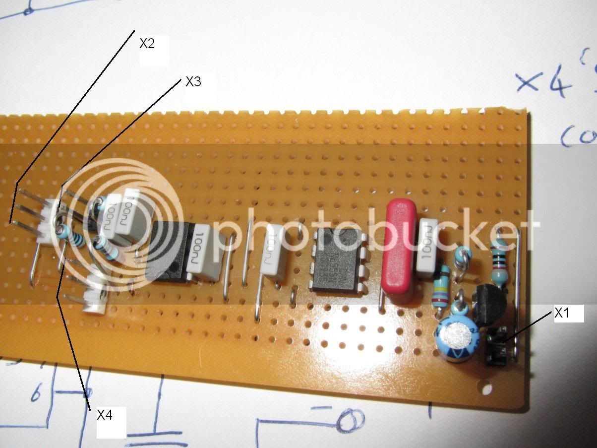
Here is the circuit put together on stripboard
verohall2ESCjpg.jpg

There is, of course a dual 555 in one package called the 556 and it's probably cheaper and neater to use one of those - the component values stay the same but pin connections have to be translated. I just used what I had to hand.
It is easier to make and debug the circuit with the aid of a scope, but this one is simple enough to have a go without if you're feeling brave..... make the BEC first - ensure it's supplying 5V when the input is 8V and over. Then make the astable & confirm the 20ms timebase. Then make the monostable part.

Just to make clear what the various plugs are:
X1 is 8V to 35V supply for if your ESC does not have a BEC - you can connect this to the bottom few cells of your main battery. It only takes a few mA so the extra dreain on those bottom cells is negligible.
X2 connects to the hall throttle Signal, 5V and GND
X3 is a shutdown input. This is to allow a battery monitor (eg the celllog from HK - hint hint) to stop the motor from utterly discharging your lipo's... It is configured to connect to an "open collector" or dry contact.
X4 is the "servo drive" connection to the ESC Signal 5V and GND
 
Hey guys.
I am very new to the electronics world and have started work on a 18s balancer using fan cooled resistor modded battery medics, and cell-logs for hvc. I appoligise now, for how neewbish this is probably going to be....

So far I have completed most of the design, and the hvc and balancing are working wonderfully. But I have come a little stuck with how to power the fans.

Ideally I would like to use a 3p2t switch and have the choice between running the fans from the individual packs, or from the 12v supply that powers my fans and display for my meanwells.

Like i said I am very new to all this, but i'm pretty sure the common ground in my circuit between the packs and 12v supply is whats causing the problem and magic smoke.

Here's an abbreviated terribly drawn version of what im trying to do.

balancerfans.png


So i already fried a jst connector on the 7th pin so im pretty sure its the ground because it all in parallel or whatever.... what can i do to stop this?
Is there an easy way to prevent the short circuit using schottys or something?
I really dont know where to go from here or what to try and still keep the whole thing simple so any advice or ideas from you guys would be awesome.
I could always choose just the power supply or just the battery packs to run the fans but wheres the fun in that? haha

Thanks for any help guys :)
 
The negative wire from your 12v power supply is going to both packs (I think). This will be shorting the bottom pack and make smoke, etc. You could disconnect the packs from each other to solve this, or better would be to use two separate switches, one for each fan.

Here is a badly hacked diagram showing the top setup. The bottom one could be wired the same way. With the switches in this configuration, the 12v supply is never connected to the packs.

 
Thanks Fetcher.
I was hoping I could get away with one switch somehow but I guess not. I guess i'll have to decide if the switches are even worth the hassle.

Thanks again Fetcher, I was sure that was the problem, but was hoping there was maybe some other way to solve it.
 
first sorry for the bad english i is not my first language.

I want to make a circuit that switch a relais when paddeling a bike with a PAS sensor (The one with the hall sensor and 5 magnets).

My bike have a throttle witch i mod to only 6km/h, and a PAS sensor. When i use the throttle i go 6km/h. When i go paddeling the bike go to 25km/h.

The blackbox in the next link is wat i want to make. I only need to know how to make the black box. the 6km/h throttle already works.

https://picasaweb.google.com/lh/photo/1zmQHLeqDOO1ZBktd0xvA6ULnDLCIaMURKU3Jppa_wM?feat=directlink

My problem is that it is possible 5V or 0V when not paddeling.
You don't know if there is a magnet for the PAS sensor or not when not paddeling.

Can somebody help with the circuit. I like to be roadlegal (paddel first) and use a throttle to regulate the power.
 
@Erikjan

If you don't mind doing a little programming I would use an Arduino uC, like this:
eBay Arduino Nano US$17

Read up here on how Arduino works: http://www.arduino.cc/

I would have both the throttle and PAS as inputs to the Arduino (Throttle as an analog in, and PAS on one of the digital interupt ins).
And then have an analog out create the throttle signal you need.

Then it would be fairly easy to set up the logic in the code to meet the black box functions you outlined.

- Adrian
 
Thanks for the idea i have one of the arduino uC from an ohter project.
I go try to write the program. I never done that. For the other project (home control system) i only have to
download the software an upload it in to the controller. Now i have to make my own program.

I have one of this:
http://cgi.ebay.nl/Arduino-Duemilanove-Clone-ATmega328-D-Robotics-UK-/140600731385?pt=UK_ToysGames_RadioControlled_JN&hash=item20bc74e6f9

I think it can do the job it is only bigger. If it works i buy the small one.
 
Have a look at this example it uses interupts and calculates RPM, that should be most of what your code needs to do.
If you need to know road speed you will also need a normal bike computer wheel sensor for wheel rpm.

http://www.arduino.cc/playground/Main/ReadingRPM

Let me know if you need any help

- Adrian
 
Back
Top