Doctorbass
100 GW
I bought it and received it a week ago.
i'll try to review it and make some modifications to it.
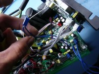
I communicated with Jack Xie to confirm the adjustment potentiometer inside
W503 is for voltage
W401 is for end of charge current cut off adjustment
W402 is also for current adjustment ( probably the fine or coarse)
W4011 is also for voltage adjustment ( probably the fine or coarse)
W501 is for LED lamp indicator ajustment.
I had succed to adjust it to 12V to 105V and keep it stable.
I asked them for adjusting it for 100.8V and 15A.
They confirmed me that they can take 3% more for the current and for the voltage.. but i doubt about these data and i'll confirm. because they said it'S +/-3%.. but i acheived from as low as 12V to 105V.. so 12V is far lower than -3%.
I successfully installed an external panel mount potentiometer 10 turn Bourns quallity potentiometer fo rthe voltage and i'll make the same for the current...
That will make it like a lab power supply... :lol:
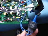
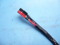
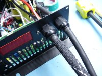
Mod 1: I also removed the original output cable and the input AC cable and replaced with quality CSA and UL 14/3 rubber flexible cable and quality Hubblle AC plug. This remove some weight to the charger cause the cheap chineese 2.5mm wires are too heavy for nothing and are not certified. And for the DC output, I installed ultra flexible 10AWG turnigy silicone wire and a good look protective aerospace looking skin!
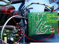
Mod 2: Also .. for those who wonder if it is possible to make it giving power output WITHOUT the need to connect a battery to the lead and having this &?&?(&*!!! voltage detection circuit bypassed.. I say... YES it work... it's just a relay that is activated by teh presence of a battery with the right voltage range...
Mod 3:I also installed a jumper to the transistor that control the two powerfull blowers. I dont trust chinese electronic stuff of that power used in intermitent non cooled conditions!
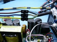
Mod 4: I beefed up the traces of the power section with 10AWG euivalent ground cable
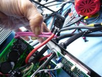
Mod 5:I am also installing some voltage sense to the output connector at the end of the output cord. By this way, my charger will push current longer period in the CC state ad charge the battery faster. Voltage sensing avoid the voltage lost in the output cord.. so the charger se the real voltage of the battery while pushing high current to it... and dont have the 0.1 to 1V loss in the wire that make the charger thing the battery is0.1 to 1V higher tha it really is!
This is the most complicated part of the mod. Usually all my meanwell have S+ and S- connection for the voltage sensing.. but these cehap chineese charger dont have this option as well...
I connected two additional little and twisted wires between the output charging connector and the charger circuit near the voltage feedback measurement is done in the PWM circuit.
What voltage sense make?.. let say the chrger is not connected to any load and that i measure 100.0 V
Than i connect a load to the charger to draw let say 15A... usually with teh voltage loss in the cable the real voltage i will measure at the end of the cable and near the load will decrease a bit and be probaly 99.5V depending on the wire size i used.
But with the voltage sensing feature the voltage near the load will stay 100.0V .. that fact will make the battery to keep being charged for more time at full curent! :wink:
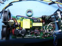
Mod 6: I installed some silicon to to secure the loose parts from vibrations like the capacitors, transformers, inductors etc.
MOd 7: I also installeld some MS222 threadlocker to the nut that keep in place the transformer cause they was loose!!
Mod 8: I added a 4.7K 5W resistor in parallel to the output capacitor to discharge them faster when i turn down the voltage adgistment.. That clamp down the voltage and that avoid waiting that the capacitor discharge too slowly and keep the display to indicate higher voltage than the new adjusted V setpoint... A kind of simple crowbar circuit
Mod 9: I also added a Doc proof Diode against stupid reverse connections.. This is a dual parallel diode connected in serie with teh positive output!.. As well, the voltage sensing feature i added just keep the voltage setpoit to not loose 0.5V due to the conductioing shottky diode :wink: If i add 3 dide in serie.. or 100ft long output cable, the voltage sensing feature will alays keep the right voltage at the end of the cable. ) I t compensate for any V loss)

Doc
i'll try to review it and make some modifications to it.
I communicated with Jack Xie to confirm the adjustment potentiometer inside
W503 is for voltage
W401 is for end of charge current cut off adjustment
W402 is also for current adjustment ( probably the fine or coarse)
W4011 is also for voltage adjustment ( probably the fine or coarse)
W501 is for LED lamp indicator ajustment.
I had succed to adjust it to 12V to 105V and keep it stable.
I asked them for adjusting it for 100.8V and 15A.
They confirmed me that they can take 3% more for the current and for the voltage.. but i doubt about these data and i'll confirm. because they said it'S +/-3%.. but i acheived from as low as 12V to 105V.. so 12V is far lower than -3%.
I successfully installed an external panel mount potentiometer 10 turn Bourns quallity potentiometer fo rthe voltage and i'll make the same for the current...
That will make it like a lab power supply... :lol:
Mod 1: I also removed the original output cable and the input AC cable and replaced with quality CSA and UL 14/3 rubber flexible cable and quality Hubblle AC plug. This remove some weight to the charger cause the cheap chineese 2.5mm wires are too heavy for nothing and are not certified. And for the DC output, I installed ultra flexible 10AWG turnigy silicone wire and a good look protective aerospace looking skin!
Mod 2: Also .. for those who wonder if it is possible to make it giving power output WITHOUT the need to connect a battery to the lead and having this &?&?(&*!!! voltage detection circuit bypassed.. I say... YES it work... it's just a relay that is activated by teh presence of a battery with the right voltage range...
Mod 3:I also installed a jumper to the transistor that control the two powerfull blowers. I dont trust chinese electronic stuff of that power used in intermitent non cooled conditions!
Mod 4: I beefed up the traces of the power section with 10AWG euivalent ground cable
Mod 5:I am also installing some voltage sense to the output connector at the end of the output cord. By this way, my charger will push current longer period in the CC state ad charge the battery faster. Voltage sensing avoid the voltage lost in the output cord.. so the charger se the real voltage of the battery while pushing high current to it... and dont have the 0.1 to 1V loss in the wire that make the charger thing the battery is0.1 to 1V higher tha it really is!
This is the most complicated part of the mod. Usually all my meanwell have S+ and S- connection for the voltage sensing.. but these cehap chineese charger dont have this option as well...
I connected two additional little and twisted wires between the output charging connector and the charger circuit near the voltage feedback measurement is done in the PWM circuit.
What voltage sense make?.. let say the chrger is not connected to any load and that i measure 100.0 V
Than i connect a load to the charger to draw let say 15A... usually with teh voltage loss in the cable the real voltage i will measure at the end of the cable and near the load will decrease a bit and be probaly 99.5V depending on the wire size i used.
But with the voltage sensing feature the voltage near the load will stay 100.0V
Mod 6: I installed some silicon to to secure the loose parts from vibrations like the capacitors, transformers, inductors etc.
MOd 7: I also installeld some MS222 threadlocker to the nut that keep in place the transformer cause they was loose!!
Mod 8: I added a 4.7K 5W resistor in parallel to the output capacitor to discharge them faster when i turn down the voltage adgistment.. That clamp down the voltage and that avoid waiting that the capacitor discharge too slowly and keep the display to indicate higher voltage than the new adjusted V setpoint... A kind of simple crowbar circuit
Mod 9: I also added a Doc proof Diode against stupid reverse connections.. This is a dual parallel diode connected in serie with teh positive output!.. As well, the voltage sensing feature i added just keep the voltage setpoit to not loose 0.5V due to the conductioing shottky diode :wink: If i add 3 dide in serie.. or 100ft long output cable, the voltage sensing feature will alays keep the right voltage at the end of the cable. ) I t compensate for any V loss)
Doc