Mr. Mik
1 kW
- Joined
- Sep 3, 2008
- Messages
- 390
I am continuing to test and re-condition the 102 NiMH cells in my Vectux.
It has taken 3 1/2 weeks so far, several more to follow at least....
The results of reconditioning the cells are very promising so far. And VEEEERY SLOOOOW .
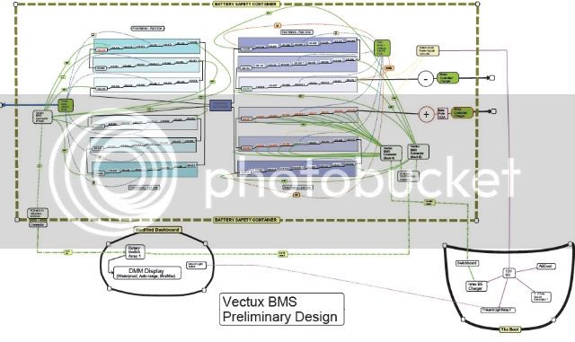
I am pondering options for a BMS = "Battery Monitoring/Managing System" or rather a " Battery Manatoring" System.
This BMS is just a plan so far.
It would in it's current form be utterly dependent on (educated) human input every step along the way, a human/machine hybrid system so to say.
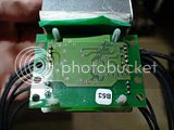
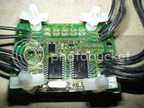
It integrates a single Paktrakr8 into the system, but more could be used.
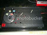
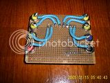
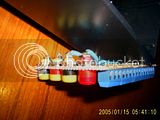
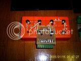
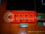
The human input (once the hardware has all materialised) will consist of turning knobs on over 30 switches...
It is definitely a geeky device. I am not sure if it is moronic or ingenious, but I'm sure it has potential!
At least my soldering will improve due to all the practice!
The cable harness might end up too thick to leave the battery compartment, or the cumulative resistance of the 6-way rotary switches is too high, or their current rating too low. Lots of potentials SNAFU's.
Here is what I think it might be able to do:
A) Monitor voltage of each individual cell if selected. But not all at the same time.
B) Log minimum and maximum voltages to the DMM for review just after riding or charging.
C) Display real time voltage to help avoid reverse charging and overcharging when the the cell most likely to experience this is switched to. The PakTrakr8 can continue to monitor any cell or blocks of them even if another voltage is shown on the DMM display.
D) Allow to find the lowest cell by systematically "zooming in" on it, even during riding.
E) Allow to recondition individual cells without taking the scooter apart.
F) Allow recharging of individual cells, maybe even from a switchmode power supply powered by the entire string; this would dramatically increase range if one or a few cells have reduced capacity.
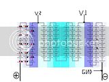
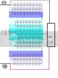
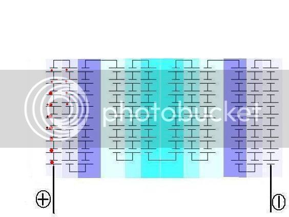
Could you please have a look at the attached PDF schematic and let me know if the design appears functional to you.
I would also like to hear about potential pitfalls before I start to build it.
The green line from the center switch is the output to the DMM or CBA2 battery analyser or the input from the charger.


