Help making mismatched throttle/controler work

Kenny'sID

100 W
Joined
Jun 11, 2016
Messages
141
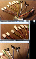
I ordered a controller for my front hub motor, the closest I could find for matching wiring and it is the proper wattage/voltage 1000/48. The hub motor hookup is pretty straight forward and even the Hall plug matches, so all is well there best I can tell.

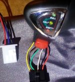
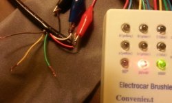
But the throttle is a different story and though the wires on the controller are labeled to a point anyway, there is no way I can tell or have the knowledge to test what goes where. I do have a multi-meter and can follow directions if that helps but will have to have step by step directions. If anyone thinks they can help me I can post what wire labeling I have and the throttle and it's wiring, or whatever pics you need. Or if you know of a site where I might get help with this, that would be helpful as well.

Even if I can just get the throttle part going and forget the indicator lights for now, I'd be happy. Also FWIW, I have two bikes I'm doing, one mountain bike and the hybrid trike I'm working on now w/4 stroke and front hub motor. I have two twist throttles exactly the same so if I can get one going with this controller, I just order the same controller for the other bike and I'm ready to go with it already. IOW, this will get two bikes going. Thanks.
 
Forgot to mention I have the little white controller tester ("Electrocar brushlessmotor Controller Tester") here, and I have heard it can test throttles, that is if that's any help at all.
 
Indicator lights?
Some pics would help. That is more than just the 3 wire throttle most controllers expect
 
Yes, the lights that indicate the full, half and empty battery capacity.

Here is the pic of the throttle and it's wiring, and the only connector on the controller that is labeled "throttle". I haven't looked too closely for the indicator wires on the controller, but for that or anything else, I also included the pic from the original listing that gives a pretty good idea of what most of the controller connectors are.

Be happy to post any other pics you might need.... I'm desperate here, lol. Thanks again

From left to right on the controller, the color is red blue and black

Hard to tell the throttle has 6 wires with the shadows...those are yellow brown green white black and red (I'm somewhat color blind but not to the point I can't see color at all, so if I'm wrong on some of the colors, that's why...and please tell me.
 

Attachments

  • s-l500.jpg
    s-l500.jpg
    41.7 KB · Views: 23,200
  • Capture.JPG
    Capture.JPG
    37.4 KB · Views: 23,199
The wires on the throttle aren't as short as they may appear, I have the full length of the harness tucked under the throttle or out of view.
 
Hi, isn't there any pin-out for the throttle?
Also, I don't see an on/off plug for controller? (usually two red wires- one brings pack voltage to a switch, and the other returns it to the controller when switch is on)

Of the 6 wires for throttle, 3 are for throttle connector to controller, and I guess the other three are for power switch/ lights. Tho I would think they would only need two wires for lights/switch though.

To test throttle, controller must be on (to test proper connection of ground, 5v, and returning 1-4v), but the indicator lights and power switch on throttle should not be guessed at until the 3 throttle wires are for sure. So first get/confirm the controller is on (sending 5v out to components), or get it on by finding the pack voltage wire and it's return wire for on/off.

Hopefully that's something to start on until someone that knows that throttle cluster and controller can give a pinout. Good luck!
 
Hi, Nutspecial, if this doesn't help, I'll try to find the wire you mention, but maybe you can help me with what I have going now. I've never used this tester but got on youtube and though my tester is labled a little differently than the on they show. IOW, mine says "steer" instead of "throttle", (you know some of that "Chinese English") but I did run the test I pictured and it showed those wires hooked up as the actual throttle wires. When I twist the throttle, the light gets brighter and brighter so that should eliminate that. Black red and white are hooked up, leaving a brown (hard for me to discern that color) yellow and green to figure out. Still don't know what wires on the controller are what but maybe y'all can help me work through it this way somehow or maybe this will only get us so far, IDK.

As far as the on/off for the controller I've run into 2 wires that say "cruise" on the controller, and until now I guess I assumed they were some type of cruse control, but could well be the ones to the power button that turn the controller off/on. On my old thumb throttle, it has two gray wires that are hooked to something on the other controllers and they are gray, just as the ones on the new controller. I'll get some more pics up tomorrow and do a few tests before I go to bed to see if I can discern the on off/wires or whatever, but I'm not hooking the controller to power till I'm reasonably sure. Already fried one by being an idiot and that one was matched, and all worked well until I moved the system to another bike so, I'll be sick if I do that to this one at $50 a pop.

Just wanted to get this up for now and be back tomorrow. Oh, and here is a link to the tester instructional...still looking for a better one but I think that's as good as it gets on youtube anyway.

https://www.youtube.com/watch?v=-rPKBfC7xfc#t=26.36
 

Attachments

  • Capture.JPG
    Capture.JPG
    33.5 KB · Views: 23,166
https://endless-sphere.com/forums/viewtopic.php?f=31&t=20413&start=75 There is a pdf with instructions on using the tester in this thread. In the video that you linked, the instruction to turn the key switch on = connect the controller thin red wire ( door lock switch ) to battery positive.
 
Kenny'sID said:
The hub motor hookup is pretty straight forward and even the Hall plug matches, so all is well there best I can tell.

Beware, even when you get the throttle sorted out you can not assume hall and phase wires are correct, even if the plug fits and the colours are matched.
There is no standard for these so don't be shocked if you get jerky or no movement at all.
 
Yes, absolutely true on phase and hall combos. Get the thing to self learn, use the tester, or diy proper combos before trying to push any real amps.

If the test shows positive for black red and white you show, looks like you have the three for throttle isolated. Should be power, ground, and return signal. They'll be easy to match with proper wires on cont.plug.

The other three on throttle are a mystery to me, though pack voltage is likely for one wire, and it sounds like a second one will be the doorlock wire that signals controller on when receiving said pack voltage thru that red switch. I never would have guessed 'doorlock' lol, good tip.
 
http://www.ebay.com/itm/48V-Thumb-Throttle-Gas-Twist-Throttle-Electric-Bike-Ebike-Scooter-LED-Indicator/221450533419?_trksid=p2047675.c100005.m1851&_trkparms=aid%3D222007%26algo%3DSIC.MBE%26ao%3D1%26asc%3D20131003132420%26meid%3D788b6068be0d4ae19ed18641f3bfed05%26pid%3D100005%26rk%3D2%26rkt%3D6%26sd%3D321753412028

I decided to search ebay for 6 wire throttles (ebike throttle led). The above was the 2nd one I saw, and it looks like it uses the same color scheme as yours (scroll down for pinout). It may be rudimentary, but it's an avenue I'd explore to help figure out what goes where.
 
A few minutes searching ES with posts linked to eBay turns up this information:

ControllerCabling.png
  1. Power Cables: big red + big black
  2. Phase Cables: big yellow + big green + big blue
  3. Power-On Cable: middle red (aka 'Electric Door Lock Cable', 'ignition cable')
  4. Hall Cables: small red, small black, small yellow, small green, small blue
  5. Throttle Cables: small red + small blue + small black (aka 'Reverser' Cables)
  6. Speed Cables: blue(high speed)+ black + +yellow(low speed) (aka 'Shifter' Cable)
  7. Brake-Hi Cable: yellow (connect to 12V brake light on scooters)
  8. Brake-Low Cable: Brown or pair Brown & Black (tie Brown to Black (Gnd) to indicate braking)
  9. Anti-theft Cables:Red(Positive) + Black(power) Red(E-Start) + Blue(Motor Lock Signal) + Green(Motor Lock)
  10. Self-Study cable: two white cables with black plugs
  11. E-ABS(Optional): two blue cables matched
  12. Cruise(Optional): two Gray cables connecting together.

  • So - hook up your power cables and tie the Power-On wire to battery (+) same as the fat red power wire. A series switch can be added to this wire to implement a kill switch (good idea) or a keylock (I like to use security system switches for this).

    This should power up the controller.

  • Test your throttle with the tester by hooking up the red, black, and white wires from the throttle to the tester. The third wire on the tester is the signal wire - typically blue, but NOT the red (+5V) or black (Gnd). Turn on the tester and operate the throttle. The LEDS should change color as indicated in the document referenced above ( Using the Lyen Ebike tester). This should work. On the off chance it doesn't, try the other three colored wires on the throttle in place of the white using the tester until you identify the one carrying the throttle signal. We are looking for an output signal here and there is no more than 5V in play, so these particular trial-and-error tests are harmless...

  • With the controller running and the throttle wires identified, just hook them up. Assuming the white throttle wire is the proper one:

    6WireThrottle3.png
That should get things going once you do the 'self learn' stuff. The power indicators are another matter and deal with Vbatt(+) which can do Very Bad Things to your controller if connected improperly - not something you want to randomly connect to experiment. I'll leave that for you to sort out, perhaps with the assist of someone with actual knowledge of that throttle - not just guesses.

  • EDIT - Also, in the absence of a 3-position switch, you may wish to jumper the blue and black wires of the 'Speed Cable' to remove any power limitations from the default medium power setting that is in play when nothing is connected. Sort of depends on controller programming, but harmless to try if you are not getting full power. These 3-position switches are really just SPDT on-off-on center-off switches if you want to rig one yourself with available parts (black to the middle wiper, blue and yellow to the end contacts for High and low respectively).
 
nutspecial said:
Hi, isn't there any pin-out for the throttle?
Also, I don't see an on/off plug for controller? (usually two red wires- one brings pack voltage to a switch, and the other returns it to the controller when switch is on!

Not positive but the red electric door lock wire looks like it could be the on/off. That would have to be touching the positive wire to turn the motor.

Also your throttle colors are of the standard color code. You only need red black and white for controlling the throttle.
Red is 5v
Black is ground
White is signal wire
Green activated the led power meter on the throttle if wired to posistive

And brown/yellow are the on/off button which you can use for anything. It should be a maintained switch

The only question is what three wires on your weird controller are you supposed to use to connect it?

You would think it to be the shifter cable or the reverser cable.
 
skeetab5780 said:
Also your throttle colors are of the standard color code. You only need red black and white for controlling the throttle.
Red is 5v
Black is ground
White is signal wire
Green activated the led power meter on the throttle if wired to posistive

And brown/yellow are the on/off button which you can use for anything. It should be a maintained switch

The only question is what three wires on your weird controller are you supposed to use to connect it?

You would think it to be the shifter cable or the reverser cable.

Those colours are correct. The red button is often used for the ignition wire. You connect either the yellow or brown to the battery positive and the other wire plus the green to the ignition wire on the controller, which in this case id the red "power on" wire. That way, the throttle LEDs come on when you switch the controller on.

All the reverse functions that I've seen on controllers had only two wires: Unconnected for normal operation; connected for reverse.

All similar controllers I've seen had a PAS function.

I'm not convinced at all by those Chinese descriptions of the wires.
 
Wow, just skimmed it, but what a bunch of helpful info, thanks so much everyone.

Life got in the way today so didn't get back as soon as I'd hoped. I'll take a closer look at all of it and comment if I can later or definitely by tomorrow. I'm now pretty confident we can get it going.

Y'all made my day....seriously. :)
 
Kind of stupid of me for not getting this up there from the beginning.From let to right, the labels on the wires/connectors themselves

1) Anti-Theft- 3 wires
2) throttle
3) Three Speed
4)Phase cable
5)Brake-Lo
6)Brake Hi
7)Lock Cable
8)No label (single green)
9)Self-Study (two whites, w/mating male/female connectors
10)E-ABS Cable (2 dark wires, black or dark blue? also w/mating male/female connectors
11)Cruise Cables ( two gray wires, w/mating male/female connectors
The remainder in the bundle on the end right is hall sensor, power, and motor phase wires... they plug up fine.

Not sure what the deal is with the mystery smiley taking the place of no. eight, but he's persistent beyond my ability to get rid if him.
 

Attachments

  • wire.JPG
    wire.JPG
    100.3 KB · Views: 23,104
aroundqube said:
https://endless-sphere.com/forums/viewtopic.php?f=31&t=20413&start=75 There is a pdf with instructions on using the tester in this thread. In the video that you linked, the instruction to turn the key switch on = connect the controller thin red wire ( door lock switch ) to battery positive.

Thanks, and the PDF will come in handy.

Gregory said:
Kenny'sID said:
The hub motor hookup is pretty straight forward and even the Hall plug matches, so all is well there best I can tell.

Beware, even when you get the throttle sorted out you can not assume hall and phase wires are correct, even if the plug fits and the colours are matched.
There is no standard for these so don't be shocked if you get jerky or no movement at all.

I won't be. You are right, this is the big drawback at this stage with ebikes, things are not like they should be. On some of these controllers, there are even plugs that can be plugged and burn the system unlike the standard in the US where if it plugs up, it shouldn't burn up.

nutspecial said:
Yes, absolutely true on phase and hall combos. Get the thing to self learn, use the tester, or diy proper combos before trying to push any real amps.

If the test shows positive for black red and white you show, looks like you have the three for throttle isolated. Should be power, ground, and return signal. They'll be easy to match with proper wires on cont.plug.

The other three on throttle are a mystery to me, though pack voltage is likely for one wire, and it sounds like a second one will be the doorlock wire that signals controller on when receiving said pack voltage thru that red switch. I never would have guessed 'doorlock' lol, good tip.

I did have a bad controller on one system that I was refunded on, and the wheel shook badly from a dead stop but straightened out onece I put it on the road and got it up to speed. However, I barely got back up the hill with it when comoing home with plenty of power in the bvatteries. Then once I was refunded for the kit, I was free to try another good controller at my own risk and the wheel worked fine, so could have been the halls were just offset or the controller was bad. All that leads to the question, is it ok to at least try it and see if the wheel shakes and if it doesn't, just assumer all is well with the Halls, or do I need to do the Hall testing before I even try a little power to the wheel?
 
So 'shifter' = 3 speed.

'door lock' = ignition.

So you can confirm proper hall/phase combos (depin and repin connectors if necessary- I'd imagine self study and/or tester should be handy here) . .

And power controller (temp connect ignition to battery +) . .

And get throttle operational (from your tests, looks like red to red, black to black, white to green). .
__________________
Then finally run ignition and a battery + wire up to the remaining wires on throttle.
__________________
d8veh knows his stuff. I didn't quite follow the instructions/idea for led/switch though:

Try yellow and/or brown to battery + ?
Try ignition to remaining green ?
I wonder what the left over wire is for then?

It would seem the led's or their driver need to see full pack voltage, and so should the switch. That's just two wires though, one coming and one going.
Unless a ground is also needed for the lights/driver?

PS 8) Lol, cool guy is persistent :lol:
 
I missed your last post there.
is it ok to at least try it and see if the wheel shakes and if it doesn't, just assumer all is well with the Halls, or do I need to do the Hall testing before I even try a little power to the wheel?

I tested mine that way, but don't ride it unless you're sure. Be careful not to overheat when testing also, it will burn amps when firing out of order. Plenty of people do it that way, but if you have a tester you can use that if desired, and before anything try that 'self study' function. There should be directions, but I'd imagine you just plug it in for a while, maybe lightly do some throttle, then disconnect and see if everything is copacetic.

The other mating plugs only need mated if you want those functions. Beware of cruise.
 
nutspecial said:
http://www.ebay.com/itm/48V-Thumb-Throttle-Gas-Twist-Throttle-Electric-Bike-Ebike-Scooter-LED-Indicator/221450533419?_trksid=p2047675.c100005.m1851&_trkparms=aid%3D222007%26algo%3DSIC.MBE%26ao%3D1%26asc%3D20131003132420%26meid%3D788b6068be0d4ae19ed18641f3bfed05%26pid%3D100005%26rk%3D2%26rkt%3D6%26sd%3D321753412028

I decided to search ebay for 6 wire throttles (ebike throttle led). The above was the 2nd one I saw, and it looks like it uses the same color scheme as yours (scroll down for pinout). It may be rudimentary, but it's an avenue I'd explore to help figure out what goes where.

Thanks, I didn't even think to do that...I'll take a look at it and it should be helpful. Rudementwery is good here. :)

teklektik said:
A few minutes searching ES with posts linked to eBay turns up this information:

View attachment 1
  1. Power Cables: big red + big black
  2. Phase Cables: big yellow + big green + big blue
  3. Power-On Cable: middle red (aka 'Electric Door Lock Cable', 'ignition cable')
  4. Hall Cables: small red, small black, small yellow, small green, small blue
  5. Throttle Cables: small red + small blue + small black (aka 'Reverser' Cables)
  6. Speed Cables: blue(high speed)+ black + +yellow(low speed) (aka 'Shifter' Cable)
  7. Brake-Hi Cable: yellow
  8. Brake-Low Cable: Brown
  9. Anti-theft Cables:Red(Positive) + Black(power) Red(E-Start) + Blue(Motor Lock Signal) + Green(Motor Lock)
  10. Self-Study cable: two white cables with black plugs
  11. E-ABS(Optional): two blue cables matched
  12. Cruise(Optional): two Gray cables connecting together.

  • So - hook up your power cables and tie the Power-On wire to battery (+) same as the fat red power wire. A series switch can be added to this wire to implement a kill switch (good idea) or a keylock (I like to use security system switches for this).

    This should power up the controller.

  • Test your throttle with the tester by hooking up the red, black, and white wires from the throttle to the tester. The third wire on the tester is the signal wire - typically blue, but NOT the red (+5V) or black (Gnd). Turn on the tester and operate the throttle. The LEDS should change color as indicated in the document referenced above ( Using the Lyen Ebike tester). This should work. On the off chance it doesn't, try the other three colored wires on the throttle in place of the white using the tester until you identify the one carrying the throttle signal. We are looking for an output signal here and there is no more than 5V in play, so these particular trial-and-error tests are harmless...

  • With the controller running and the throttle wires identified, just hook them up. Assuming the white throttle wire is the proper one:
That should get things going once you do the 'self learn' stuff. The power indicators are another matter and deal with Vbatt(+) which can do Very Bad Things to your controller if connected improperly - not something you want to randomly connect to experiment. I'll leave that for you to sort out, perhaps with the assist of someone with actual knowledge of that throttle - not just guesses.

  • EDIT - Also, in the absence of a 3-position switch, you may wish to jumper the blue and black wires of the 'Speed Cable' to remove any power limitations from the default medium power setting that is in play when nothing is connected. Sort of depends on controller programming, but harmless to try if you are not getting full power. These 3-position switches are really just SPDT on-off-on center-off switches if you want to rig one yourself with available parts (black to the middle wiper, blue and yellow to the end contacts for High and low respectively).

Thanks a bunch. I'm going to let y'all look the pics I just posted and if there are no additions/changes in advice, I'll get on that.

skeetab5780 said:
nutspecial said:
Hi, isn't there any pin-out for the throttle?
Also, I don't see an on/off plug for controller? (usually two red wires- one brings pack voltage to a switch, and the other returns it to the controller when switch is on!

Not positive but the red electric door lock wire looks like it could be the on/off. That would have to be touching the positive wire to turn the motor.

Also your throttle colors are of the standard color code. You only need red black and white for controlling the throttle.
Red is 5v
Black is ground
White is signal wire
Green activated the led power meter on the throttle if wired to posistive

And brown/yellow are the on/off button which you can use for anything. It should be a maintained switch

The only question is what three wires on your weird controller are you supposed to use to connect it?

You would think it to be the shifter cable or the reverser cable.

More very helful advice...thanks. Gonna take me a bit of study to get things sorted out here but I'm sure this will come in handy.

d8veh said:
skeetab5780 said:
Also your throttle colors are of the standard color code. You only need red black and white for controlling the throttle.
Red is 5v
Black is ground
White is signal wire
Green activated the led power meter on the throttle if wired to posistive

And brown/yellow are the on/off button which you can use for anything. It should be a maintained switch

The only question is what three wires on your weird controller are you supposed to use to connect it?

You would think it to be the shifter cable or the reverser cable.

Those colours are correct. The red button is often used for the ignition wire. You connect either the yellow or brown to the battery positive and the other wire plus the green to the ignition wire on the controller, which in this case id the red "power on" wire. That way, the throttle LEDs come on when you switch the controller on.

All the reverse functions that I've seen on controllers had only two wires: Unconnected for normal operation; connected for reverse.

All similar controllers I've seen had a PAS function.

I'm not convinced at all by those Chinese descriptions of the wires.

Thanks for the verification...the more I know the less chance of frying things. If that should happen it's all on me of course, as I will make the decision to act with the info but all suggested will give me a much better chance at avoing that than I would have had on my own.

This may be a stupid question...though I am awaithing my fuses to come in the mail before I get to drastic with testing I have noticed that won't protect me from everything. For some reason I have this idea if I just connect with a single strand or 2 of the braided wire for testing, and if there is a burn, it will likely burn the wire up before anything critical or the wire acts like a fuse. Is that logical thinking or just wishful thinking? Anyone ever do that?
 
nutspecial said:
So 'shifter' = 3 speed.

'door lock' = ignition.

So you can confirm proper hall/phase combos (depin and repin connectors if necessary- I'd imagine self study and/or tester should be handy here) . .

And power controller (temp connect ignition to battery +) . .

And get throttle operational (from your tests, looks like red to red, black to black, white to green). .
__________________
Then finally run ignition and a battery + wire up to the remaining wires on throttle.
__________________
d8veh knows his stuff. I didn't quite follow the instructions/idea for led/switch though:

Try yellow and/or brown to battery + ?
Try ignition to remaining green ?
I wonder what the left over wire is for then?

It would seem the led's or their driver need to see full pack voltage, and so should the switch. That's just two wires though, one coming and one going.
Unless a ground is also needed for the lights/driver?

PS 8) Lol, cool guy is persistent :lol:

Thanks that clears things up even more. And on the test, that's kinda what I figured, test the wheel for vibration but best not do a road test unless it feels right? right?

And I got cool guys number now, have him all figured out, but he can stay as long as he behaves. :)
 
OK, got some success in a round about sort of way.

First I used a thought bad controller for the test...one I had fried some wires on, rewired it and tested it before with no success, but thought there was a chance I burned up the original thumb throttle and the rewired controller might still be ok. Or in short, try a possible working old controller first just in case. Hooked the wires per the diagram Teclectic provided me, had some of the wires plugged to the old thumb throttle, and turns out they must be the power as I had completely forgotten to hook any power wires in the rig.

Anyway, with old thumb throttles power button engaged, no lights on either throttle, the twist throttle engaged the wheel. A couple of quick tries with no shimmy/shake and plenty of oomph.

So, I think the smart thing to do here since we don't know what the wires are for the indicator lights on the twist throttle, is to order an exact duplicate of the thumb throttle, the one that plugs right up to the old controller, hope everything...lights and all, works. Then use the new controller for the other bike.

Only drawback is it seems to me a twist throttle would be so much better than a thumb. I guess I'll pull the thumb throttle apart first in case there are burnt wires and save myself 18 to 20 bucks, otherwise, not much to spend to be fairly certain all will be well and everything will plug up as it should, at least on the trike.

Off topic but I just found the gas engine coming in tomorrow is too big for my state as we have to have any gas bike inspected and registered and they just did start even allowing them in Fl. What is wrong with these people, how bout some incentive to save gas? I just wonder if a 49cc is going to be worth putting on this bike or maybe I'll try to slip by with a 49cc sticker on the 3 horse and they won't catch it.

Thanks again all, I'll do some occasional updates and any other input on the twist throttle is welcome as I will be using it eventually on the other bike and some indicator lights would be nice. Not to mention I actually have one more front hub motor that I will eventually get another controller and bike for so I can easily sell it...won't do any good just sitting there and I have another twist throttle I can use for it.
 
OK, the new thumb throttles that are an exact match do not match on the wiring so that's out, and back on trying to get the twist throttle to work here.

As mentioned by someone, the yellow and the brown on the throttle are to the power button, as a continuity test verified, I also followed the wires to the old thumb throttle and somehow, don't remember how, found the two wires from the controller for the power, tested it and no fry. Works good with just the twist throttle now but with no indicator lights. There is one wire left on the twist and since the indicators are still non functional (full half and empty) it was probably mentioned that last green wire from the throttle is for the indicators.

Now for what wire from the controller to attach to that last green indicator light wire from the throttle? Or can I come directly off the battery for that? If not, I'm looking for what kind of reading with the multimeter to tell me what wire from the controller is right for the indicator lights? I have it narrowed down by what wires are left that went into the old thumb throttle. I'll have to look again, but there my be only a couple or three. I'll rest my mind again, and I might even be able to narrow it down to the one when I go back.

Almost there, just one wire to go. If worse comes to worse, I have a tiny volt/amp meter that I can mount somewhere to do the job but it would be nice to get this all like it should be. I've been using the very thin wires as fuses like I mentioned earlier so it's very likely, even if I hook it wrong, I'll be able to pull it fast enough or the small wire will burn and no damage will occur.
 
I gave you a procedure to figure the throttle out using the tester if we didn't have a clue (which I didn't) , but then we had this:

d8veh said:
skeetab5780 said:
Red is 5v
Black is ground
White is signal wire
Green activated the led power meter on the throttle if wired to posistive
And brown/yellow are the on/off button which you can use for anything. It should be a maintained switch

Those colours are correct. The red button is often used for the ignition wire. You connect either the yellow or brown to the battery positive and the other wire plus the green to the ignition wire on the controller, which in this case id the red "power on" wire. That way, the throttle LEDs come on when you switch the controller on.

d8veh is a good source for this sort of stuff and skeetab is in agreement, so we got verification for the basic throttle and the missing information for the power and LEDs. Based on their info, you need to do this:

6WireThrottle3.jpg
(Depending on how you have things wired so far, you can interchange the yellow and brown wires - they're just opposite sides of the power switch.)
 
Thanks for making that so clear, Tek.

And Thank you Dev for clear instructions. I sometimes miss things and should have read closer before I posted again. It was there all along...twice. I do well on most things but tend to get confused easily when it comes to wiring. I can usually get it, especially with good instruction like here, but I have to walk away several times and come back...easily overwhelmed.

Learning a lot of valuable info for applying to the other bike/bikes too.

I'll report back tomorrow after I try it.
 
Back
Top