Help making mismatched throttle/controler work

I've added the green in with the yellow and I get the initial snap/arc that is normal but I also get that everytime I give it battery power, not normal. The "empty" indicator light comes on and eventually fades off when I disconnect.

I'll look the info here over again, as I'm sure I just missed something knowing me, but just wanted to get what was happening up here FWIW.
 
I've had the yellow wire connected to a small yellow wire from the controller up to now to make everything function as it did. From the diagram, I take it I need to remove that and connect it directly to the 48v battery line before the controller...right?
 
Kenny'sID said:
I get the initial snap/arc that is normal but I also get that everytime I give it battery power, not normal.
I don't understand. What is arcing? There may be an arc when you connect the battery, but what does 'give it battery power' mean? Where is it arcing then?

Kenny'sID said:
I've had the yellow wire connected to a small yellow wire from the controller up to now to make everything function as it did.
This should not have done anything. The thin yellow wire is the "brake hi" signal and is usually unused on ebikes. Are you saying you needed to connect that to make something work? To make what work?

Kenny'sID said:
From the diagram, ... I need to remove that and connect it [the yellow throttle wire] directly to the 48v battery line before the controller...right?
Yes.
The diagram is all there is - the picture shows exactly what is required - nothing more - nothing less. Don't wing it and start hooking up other stuff.

As I said many posts back, messing with full battery voltage around the controller can have bad consequences. The controller signals work with 5V - if you also had that yellow 'brake in' wire connected when you tied in the full battery voltage then there's a chance Bad Things happened... hopefully if you fried something it was only the 'brake in ' circuitry - which you don't need anyway...
 
When I said arc, I meant it did the usual snap/spark when connected. That normal snap only happens once unless one waits for a substantial amount of time, but in my case it kept happening each time I connected it. I'm sure it was just the yellow wire I had missed.

I now have them to what I think is right and all works (power switch engages power and twist of throttle engages wheel) but the 3 leds are on full time whether the switch on the throttle is on or off.

Here's what I currently have on the wiring in case I'm missing something, and I could very well be.

I have the yellow temporarily twisted with green since we agreed they were interchangeable. Also there is a purple that was originally brown coming from the controller...I believe that's the power on wire. That was due to the rewiring of the controller and having no right color wires to replace them with.
 
Kenny'sID said:
I've had the yellow wire connected to a small yellow wire from the controller up to now to make everything function as it did. From the diagram, I take it I need to remove that and connect it directly to the 48v battery line before the controller...right?

Evidently no, I did not need that connected where it was, as things still work just as they did since I moved it to where the diagram says to. That is with the exception of the fact I now have LED's on but as I mentioned, in an always on condition, whether the power switch is on or off.
 
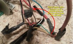
Leave everything the way it is -except- move ONLY the green throttle wire as shown below so it is connected to the brown throttle wire instead of the yellow throttle wire. Leave the brown and yellow wires otherwise attached where they are.

( Getting there a step at a time... :D )

throttleStuff2.jpg
 
teklektik said:
Leave everything the way it is -except- move ONLY the green throttle wire as shown below so it is connected to the brown throttle wire instead of the yellow throttle wire. Leave the brown and yellow wires otherwise attached where they are.

( Getting there a step at a time... :D )


A step at a time is fine with me...no complaints here whatsoever.

I now have all the lights come on when I engage the power button, or in short, it comes on when I turn it on so one step closer, but all lights are on at a time and we need just one at a time unless I'm missing something (either full half or empty
 
I propped the bike up and ran it, and the "full" light goes off as it runs at a fairly high speed. I just don't recall how these lights are supposed to act. Do they all come on and then when the bike runs actually show the capacity or should they show capacity when turned on and under no load?
 
I checked out a video on the throttles and I think this one is working just as it should now. All lights evidently come on when at full capacity then they drop off one light at a time as the capacity drops. I just haven't been around these enough to remember what they did.

So, good to go I guess. :)

Thanks so much to all of you, couldn't have done it without you. Got a lot to do with this one yet...finish the electric drive then the gas, then may be back when I move to the next bike..different controller same type throttle. That is if I can't use the info here to get it going myself...might get lucky.
 
After having a little problem of pulling a short wire in the controller loose, I wrapped all the wiring up, got it ready for a test drive, and now I get wheel shake, with or without hall wires connected. the wheel actually doesn't really turn, at least not at all consistently, as if it's trying to go in both reverse and forward at the same time. I really don't get it since all was well before, so I'm thinking it has something to do with the self learn. But if that is the case, what made it get stupid? I mean why would it have to learn again? Guess I'm not clear on what self learn is, and that may not even be it.

Anyway, just wanted to get this up here, and may find a solution before y'all get to the post but if not, maybe some input will get me going.

FWIW, when I had the now solved issue of a disconnected wire, I ran the hall and phase test on the hub motor with the tester (the PDF for the tester posted here was very helpful) and best I could tell it passed with flying colors.

I should add, and I'm almost positive of this, I tried it just seconds before I plugged in the halls and I recall it lunging forward just like it should, and it wasn't till after I plugged the halls, it got wacky. I'm positive it was fine with all the other tests so I'm assuming this is something that the halls reset or whatever goes on with that. To be clear, I had not plugged the halls at all throughout all this thread, only just before I intended to test the bike.
 
Not sure about how exactly to do the self learn, but I don't see anything that looks like the self learn wires. On the new controller, they are 2 whites with matching male and female connectors, and I believe this controller had some but I guess they got absorbed when we did the throttle wiring? At any rate there are no matching male/female connectors on this controller now, the book doesn't even mention self test and I have no diagram that shows what's what on this controller with the exception of the very basics..

I'll try to find a similar controller with labeled connections I guess, and maybe get a clue from that.
 
Best I can gather, most, if not all self learn wires are white, or there is no self learn at all on quite a few...that my be the case with mine.

So what if there are no self learn wires...is there another way to do that, what would I do in this situation? That is if that is even my problem.
 
Go here : https://endless-sphere.com/w/index.php/Determining_the_Wiring_for_a_Brushless_Motor
 
I just tested the controller with the tester and it shows as bad. No need to do a video as I found one that shows how the proper sequence of leds should be and compared to mine...mine is just not right..not even close. Something happened when I plugged that Hall connector up, I have little doubt about it. Might have worked forever with no hall effect but being my old abused controller, I' really couldn't trust it anyway so...o well.

Time to wire the new controller up to the other twist throttle (same as the one used here)..the controller I originally started with and first pictured in this thread.
 
I didn't notice that you were even using another controller, from the original with the self learn thing.
You could post a little of your testing sequence and results if you're not sure the current controller is bad??

Or for setting up the 'other' one:
Read up a little on self-learn function,
use your DMM and tester for unknowns,
be careful not to swap polarity anywhere (including halls red and black),
be careful not to put pack voltage anywhere it shouldn't be (like 5v circuits: hall, throttle, ebrake, etc)
apply what you learned about the 6 wire throttle,
and you should have a good start!!!
 
Yes, the old controller is bad...the results from the test left no doubt on that.

On the new one, when I get to the point I get it ready to operate, I can do a self learn if need be. On the rest of what you mention, of "testing for unknowns", not sure what you mean. I'm a little afraid to jump into too much of anything here with my limited knowledge...don't want to burn this controller up.

If I can't get this one figured out, I'll order another that comes with the throttle, something I should have done to begin with. I'm a little surprised more sellers don't have the wherewithal to sell them with matching throttles, as that's the only real problem with using any of these controllers...the phase, power, halls...or the main connections seem to be pretty straightforward on all these, whether they came with your kit or not....that throttle?, not so much. Or maybe it's that I'm one of the few dim bulbs when it comes to this stuff and most have no trouble figuring throttle connection in a situation like this.
 
No, I don't get. Going back to your first post with pictures, I thought it's already all figured out for the throttle. ((blue black red <> white black red))

The other three wires for switch and indicator led d8veh and tek helped you complete. I didn't follow all that, but you had it working.

So what is your question about the throttle and the new controller that hasn't already been answered?
 
nutspecial said:
No, I don't get. Going back to your first post with pictures, I thought it's already all figured out for the throttle. ((blue black red <> white black red))

The other three wires for switch and indicator led d8veh and tek helped you complete. I didn't follow all that, but you had it working.

So what is your question about the throttle and the new controller that hasn't already been answered?

Where do the wires go on the new controller?

The answers here were for another controller. The two controllers have different wiring set ups. If they were exactly the same, no problem, but they are not. Honestly, if I thought I could do it myself, I would. I prefer to do everything myself, and I pretty much do but some things are beyond my capacity. I simply don't know these different controllers well enough, or enough about wiring to test and figure it out. That along with the Chinese descriptions of some of these labels, as well as the possibility, even if the descriptions were clear English, the labeling could be wrong altogether....there is just no way.
 
Can someone please verify this is correct? Once I checked with the seller to be sure the power on wire was correct, seems to have gone pretty smoothly or not, we'll see. I probably didn't need to check but after I killed the first controller, well, once bitten. Thanks

If you have any trouble due to the lighting.

Red from twist throttle to the red one of the three marked "throttle" from controller

White from T throttle to blue of the three throttle wires from controller

Black from the T throttle to the black of the same three from controller

Yellow from T throttle to battery power

Brown and Green from T throttle to the red controller power on wire (the one actually marked "lock cable" on the controller
 

Attachments

  • Capture.JPG
    Capture.JPG
    34.6 KB · Views: 2,552
It's really difficult to say for sure, but looks good.

The basic background of knowledge allowing 'guesswork' for these things is the understanding and keeping of proper polarity and voltages where they belong. Take care of that during testing, following a logically safe method/order, and you'll be fine even if the guesses are off.

I know that's not what you're looking for exactly, but it's the best I can personally do. It's lookin good though, just proceed with caution concerning full pack voltage VS 5v controller (don't mix up) circuit and you should be ok. Good luck bro!
 
Kenny'sID said:
Red from twist throttle to the red one of the three marked "throttle" from controller
White from T throttle to blue of the three throttle wires from controller
Black from the T throttle to the black of the same three from controller

Yellow from T throttle to battery power
Brown and Green from T throttle to the red controller power on wire (the one actually marked "lock cable" on the controller
Yep.
Looks consistent with the throttle color coding from skeetab and d8veh and the connectors from the controller that you report.
 
Back
Top