2WD Electric Yuba Mundo Build

teklektik

100 MW
Joined
Mar 26, 2011
Messages
4,019
Location
CT, USA
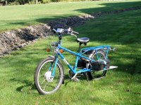
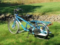
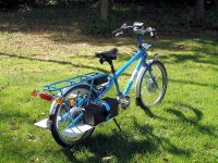
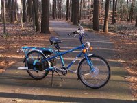
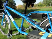
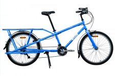
Last year I began my first build, a 2WD electric Yuba Mundo cargo bike with a relatively low power (1.7-2.4KW). The plan is to build the bike in stages: get a pretty complete bike on the road, experiment a bit with battery configurations, then finalize the battery enclosures. Stock Mundo components get upgraded as appropriate along the way. I got the first phase done and the bike on the road in mid-Fall and began evaluating battery configs this Winter. 2012 is bringing the remainder of the build.

Here's an index to posts about facets of the build.


Here’s a few shots of the bike shortly after it hit the road…
01_02.jpg
01_04.jpg
01_06.jpg
01_08.jpg
01_10_iv250.jpg
01_12.jpg
01_14_iv250.jpg
View attachment 2
01_18.jpg
View attachment 6
View attachment 1
View attachment 5
Quickie feature summary:
  • Yuba Mundo V4
  • Sun Mammoth rims with Fat Franks
    (EDIT - switched to 26x2.35 Big Bens)
  • (2) BMC V2S gear motors
  • (2) Xlyte analog 72V 35A 12 FET controllers (limited to 25A)
    (EDIT - switched to Lyen 12 FET 40A controllers)
  • (2) series 8S2P Headway 38120 packs in the sideloader
  • single Magura throttle for both motors
  • handlebar switch for one or two motor operation
  • single Cycle Analyst V2 current limit of 850W or 1700W when 1 or 2 motors are engaged respectively
    (EDIT - changed to 2000W/3300W for 1 or 2 motors)
    (EDIT - switched to CA V3 from original V2)
  • Cycle Analyst bypass switch for 1200W/2400W operation (1 or 2 motors)
    (EDIT - changed to low, med, high levels different for 1 or 2 motor operation)
  • 10A DC/DC converter
  • 55W Halogen Motorcycle headlight with 23W motorcycle turn signals
  • FIAM Freeway Blaster car horn
  • built-in front and rear LED strobes (DIY Extreme Blinkys)
    (EDIT - added ebrake-activated brake light)
  • EDIT - added CA V3-based RPM-based PAS with bar-end pot adjustment)
  • custom sideloaders
  • overnight balance charging with VoltPhreaks single cell chargers (no BMS)
Running on a single motor the bike will do about 23mph CA-limited to 850W, on two motors about 30mph CA-limited to 1.7kw, and 35 mph at 2.4kw with no CA-limiting – all speeds with an upright 200lb rider. I usually average around 17mph to keep the working range at 30+ miles at about 25-27Wh/mi with light pedaling. On the more or less flat, it runs on the rear motor alone and I switch in the front motor as needed to climb hills or sprint in traffic. It’s got about 850 miles on it to date.

EDIT - 11600mi as of Nov 2015 - See this post for updated speed/performance info.

The bike is pretty torquey over a fairly broad speed range – it responds to the throttle briskly and is quick off the line with around 90lbs of thrust from a dead stop (both motors). Since I am usually just cruising and watching the world go by, my usual mid-teens to 20mph speed is very comfortable using one motor on the sort-of-flat -- kicking in the second motor lets the bike pull up most hills with little speed change and usually throttle to spare. On-the-fly switching between one and two motors is handled with a thumb toggle – very much like shifting. A second thumb toggle disables CA current limiting for a boost. The overall biking experience is very easy and pleasurable – in part because the bike rarely seems to be working very hard and flattens most hills.

So – a couple of things to deter some immediate posts :wink:

First is the matter of 2WD. This was done for redundancy to achieve a viable ‘limp home mode’ – I don’t want to get stranded far from home with tons of groceries, a smoked motor, and a big honking steel cargo bike. I recently smoked a controller 9 miles from home, switched off the offending controller, reset the breaker, and just continued on my way. I wasn’t any too pleased it happened, but couldn’t have been happier with the 2WD choice as I motored on (2WD Grin!) .

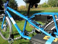
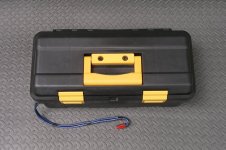
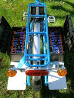
Second: the battery boxes are a bit dorky, but intentionally huge and temporary. The battery mounting issue is a major focus in every build and a major packaging effort right out of the gate seemed a poor plan – just not enough ebike experience yet. Instead, I use some cheapie toolboxes (Pep Boys) that are big enough to let me easily experiment with different XsYp configurations. The current steamer trunks and sideloaders get tossed in the next build phase.

Surprisingly, the big bike is taken as unpowered by most folks, even with the turn signals and battery boxes.
One or two 'knowledgeable' bikey sorts have commented on the big drum brakes to stop such a big bike.... :wink:
 
Getting Started

I live in a mixed rural/suburban and fairly hilly region of New England where 20% grades can be difficult to avoid and 10% grades are common. 'Level' running consists of continuous small grades - nothing is level. For this first-ever build I was looking for a simple grocery-getter cargo bike that would offer some utility, provide easy spots on the sideloaders to stash batteries, and was no speed demon. The really important requirements were hill climbing, ‘limp home mode’, and a solid 20-25 mile range.

As a noobie, there was simply an overwhelming amount of new detail to address, even with the invaluable assistance of the ES resource. A few initial decisions provided direction: a Yuba Mundo, 2WD for redundancy, gear motors for slow speed torque, and a LiFePO4 battery. I tried to research each component ‘adequately’ but there is no substitute for experience (I didn’t have) so I tried for a safe middle-of-the-road design that used proven components to get a bike that would not be cutting edge, but would be guaranteed to give good service.

Since this was to be a big heavy powered bike with a 200lb rider, I looked at features and amenities without trying to squeeze an ounce here and there – the percentages just don’t justify it. The result is big moose bike that is comfy, as safe in traffic as I could make it, and that more than fulfills my initial performance goals :wink: .

The Frame

Not a lot to say – I liked the Mundo and waited for the first V4 units rather than going with the available V3.3 models because of the 4.5lb weight reduction and the revised frame that opened up space behind the seat tube. Since I had no recent bicycle experience and I wanted to focus on the interesting EV conversion, buying the complete bike in lieu of a frame was a simple choice. I held off on disc brakes and other accessories with a plan to revisit those parts when more time and experience were in hand. The stock stuff has proven very serviceable and I am only now beginning parts upgrades.

Here's the bike specs compliments of Yuba. It has the tube sizes, etc to help get the proper size clamps and accessories:

View attachment mundospecs_v4_2011.pdf

Controllers

Although Xlyte makes a two motor controller, two independent controllers offer better redundancy and better reusability. On recommendation from Ilia at Ebikes SF (http://ebikessf.com) I use two Xlyte analog 72V 35A 12 FET controllers that are jimmied down to 25A to avoid smoking the motors. These are old-school no-microprocessor controllers that simply work. This turned out to have been a very fortuitous choice – more on this later.

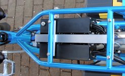
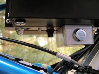
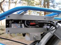
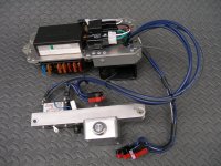
It seemed that the V4 area under the luggage rack immediately behind the seat tube was about the right size for a couple of controllers. The inserts in the Mundo luggage rack go through the tubes so threading is available on the bottom. This allows the controllers to be hung under the rack. Some 1/8” 1x1 aluminum channel provides a top mount and a similar piece at the bottom acts as a spacer and place to mount the main power switch, pre-charge button, and keyswitch.


02_02_iv250.jpg
02_04.jpg


02_06_iv250.jpg
The keyswitch is mounted in a Hammond diecast aluminum box, the lid of which is riveted to the channel. The top channel is riveted to two pieces of 1/8 aluminum bar stock to pick up the rack inserts. Steel 5mm rivnuts provide the controller mount points and are mounted flush to improve the controller mounting surface for stability. Flush mount 5mm rivnuts were backorder by everyone at the time of the build, so I used some with the regular flange and counter-bored each – kind of annoying. This really turned out to be unnecessary - a simple surface mount of the flanged rivnuts would have been fine.

The controllers are mounted with leads out the rear to minimize water entry. All controller connections are located in the space between the controllers so there is nothing exposed for meddling fingers. The bolts for the keyswitch box cannot be accessed without first removing both controllers. This is not a secure installation, but it tries to discourage casual mischief with a high PITA factor.

Breaker

Since this is a comparatively low amps/low voltage build , I use a 50A magnetic marine breaker for the main disconnect switch (Blue Sea #7230 - there are identical choices from other manufacturers). These breakers are very rugged and have been used in high humidity salt air for decades for similar double duty as protection/disconnect switches. The 7230 is rated to carry 50A, trip at 62A, is good for 65VDC, and handles interruption currents up to 7500A at 65VDC. Specs here: http://bluesea.com/productline/specs/20#td . The breaker is for controller and frame wiring protection only – the batteries have their own fuses for pack protection.

The 7500A interruption rating makes it essentially indestructible for this application. I recently had a controller short and restored power several times with recurring breaker trips before identifying and shutting down the offending controller. (Well, maybe a couple of unnecessary extra tries because I was pissed...) The CA recorded a draw of 176A. The breaker worked flawlessly and continues to do so while the two 50A MaxiFuses in the battery packs never popped. For around $15, I cannot recommend this breaker more highly.

Power Circuit

The main power wiring is plain vanilla with a conventional pre-charge setup (5W 330ohm resistor). However, the controllers offer a feature that separates the logic power from the main rail FET power so the logic can be powered down separately, leaving the caps connected and drawing essentially no power. This allows the main breaker to be left enabled to avoid doing the pre-charge business every time the bike is turned off. The controllers have a couple of extra pins on the JST throttle connector (Vbatt,logic) to accept a switch closure to enable the logic. The bike keyswitch is used to enable a Vbatt feed to the handlebar Kill switch which eventually makes its way to the logic enable pins of the controllers. The key can be removed in either position (can’t get lost or stolen) so it can be left ‘on’ and the bike run in everyday unsecure no-key mode based on the main disconnect switch alone, or in ‘public’ mode, where the keyswitch is used to disable the bike. As with the controllers, the 12v accessories require both the main breaker and keyswitch to operate.

EDIT - main power circuit was posted later in this post.

The main breaker and key switch are positioned conveniently for wiring and no effort was made to make them available from a seated position – they are for pre/post ride operation when the rider is dismounted.
 
Motors

Unlike DD, the freewheel clutch of an idle gear motor prevents paying a penalty when only one motor of a 2WD setup is powered. The clutch, low weight, and good slow speed torque made gear motors seem the way to go. A YouTube video from Cycle9 showing a two gear motor Big Dummy chewing up hills (like mine) pretty much sealed the deal ( http://www.youtube.com/watch_popup?v=pqEGkmGWMzo .

With two motors worth of torque, speed winds seemed a better choice than torque winds and so I went with BMC V2S gear motors from Ilia at Ebikes SF http://www.ebikessf.com/. Using two identical motors with identical wheels/tires has some simplifying effects that are discussed in a later post. Ilia laced them onto Sun Mammoth rims (no longer in production – replaced with the slightly narrower Rhino Lites). A couple of Fat Franks add a little suspension.

Front Torque Arm

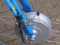
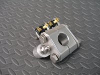
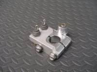
The Yuba folks use a fender stay mount to secure the torque arm for their eZee on the eMundo, but I wasn’t too happy with the short arm length. Unfortunately, the Mundo fork is not round but bladed which makes using a conventional hose clamp (I don’t like these much even for hoses…) kind of unusable since the band cannot pull smoothly around the tube – it needs to be bent with sharp angles ahead of time. This makes dropout pre-loading adjustment pretty much impossible. Instead, I use the adjuster components sectioned out of two T-bolt clamps (for turbo induction hoses) bolted back-to-back to allow parallel adjustments both inside and outside of the bladed fork tube. These use very thick SS bands and are way overkill, but the fabrication is simple with a cutoff wheel. Use small 1.5"-2.0" T-bolt clamps (eBay "T-bolt clamp") so the adjusters are smallish and get clamps with flat bands instead of those with formed edges.

03_02_iv250.jpg
03_04_iv250.jpg
Since this was a first build, for a few bucks more I overdid it and doubled up with two Ampedbikes torque arms. SS Nylocks keep everything together and allow adjustment to first rotate and preload the axle in the dropout, tighten the axle nuts, then bring up the torque arm tension to remove the slack so both dropouts and torque arm share the load.

The Ampedbikes torque arms are very cool and will align with almost anything. The trick is that if you need a position halfway between two teeth, just flip over the inner toothed piece and the alignment will shift 1/2 tooth spacing :)

When mounting the front motor, I ground out the supplied torque washers (Dremel) to exactly fit the lips on the dropouts instead of using C-washers. The result is a closed washer that holds the axle in the dropout unless the nut is unscrewed quite a bit to let the washer slide up and out over the lips. A thin SS washer on the inside of the dropouts keeps the narrow BMC axle shoulder from sinking into the dropout. To get a tight fit to the axle, I opened up 12mm SS washers a tad with a Dremel sander drum so the washers screwed easily down the threads of the 14mm axle.

BMC front motors use doubled phase wires as soon as they leave the hub. I shortened these a few inches later and installed Andersons which mate to a 10ga wire extension to run back to the controller.

Rear Torque Arm

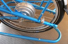
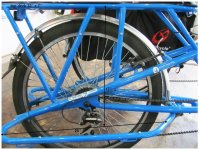
The rear motor situation on the Mundo is pretty much a nightmare: the standard axle is 14mm so hub motor axle flats don’t work and the dropouts are cluttered up with stays, making conventional torque arm attachment difficult. Unfortunately, at the time of this build, Kiwi had not yet designed his spiffy rear torque plates for the Mundo V4 so I went after this a couple of ways, including working with Yuba on a custom Mundo-specific adapter design. In the end, Yuba went with a different more generic design which is sort of a torque washer on steroids.

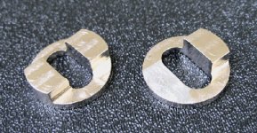
After doing an install with the new Yuba Mundo Torque Washers, I was not that happy with the axle relocation that the washers introduced (about 5/8" forward and 1/4" downward). They cut down on the clearance for balloon tires and do little to make the derailleur and rear disk brake happy. To fix this, I had a local auto machine shop remove one lobe from each washer so the motor shaft seats in the original axle position at the bottom of the dropout slot. This cost about $30 and took a only day with just a verbal description of the job.

03_06.jpg
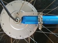
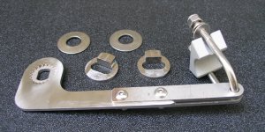
With the shaft size addressed by the Mundo Washers, a standard torque arm was added using an AmpedBikes universal arm with an extension to clear the trailing portion of the rear dropout (the only change to the AmpedBikes arm was to open up the existing holes with a #8 bit for a close fit for 5mm bolts). The SS extension shown was fabricated from a couple of donor torque arms.

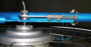
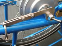
To get both the washers and the torque arm to share the load, the anchor point of the torque arm needs to be made adjustable. This allows the motor shaft to first be rotated to pre-load the washers in the slot, then the axle nuts are run down, then the torque arm can be adjusted to just snug up play. This adjustment needs to revisited over time as the components deform slightly. An easy off-the-shelf solution is to use a SS 1.25" saddle clamp (DX Engineering http://www.dxengineering.com/Parts.asp?ID=10&PLID=14&SecID=1&DeptID=39&PartNo=DXE%2DSAD%2D125A) refitted with Nylocks so the length of the u-bolt to saddle can be adjusted.

03_08.JPG
03_10.JPG
03_12opt.jpg
03_14opt.jpg
This 'adjustable' solution really only makes sense for gear motors because they freewheel and the clamp is always held under tension - there is no regen/braking to apply a reverse torque... However, as shown in an image above, the torque arm extension can be arranged to contact the chain stay, allowing the clamp to simply be run down tightly for direct drive motors.

As with the front, this conversion uses a BMC V2S motor which has a 17mm motor shaft. The configuration of the Mundo Washers leaves only two small areas of the shaft (top and bottom) to rest on the inside of the dropouts instead of the much larger areas over the flatted portions of the shaft as is usually the case (i.e. (17mm-14mm)/2 = 1.5mm shoulder width). Running down the axle nut with much torque risks sinking the shaft into the dropout. A pair of thin stainless washers inside the dropouts give a large contact area to fix this. I used the same reworked 12mm washer gimmick as on the front to get a snug fit and pick up as much axle shoulder as possible.

EDIT: Please see Oops – Rear Dropout Washers for revised washer solution.

Kiwi rear torque plates are now available and provide a tidy fabrication-free solution, but this got my build moving along fairly easily using other available parts.

Both torque arms are overbuilt (particularly for no regen) but the small extra cost and effort has been worth it for peace of mind. After 850 miles they haven’t budged even with 1500W per motor (not recommended – but fun!).
 
Batteries, Enclosures

From the outset I wanted to build some ‘thick sideloader’ decks to hide the batteries and free up deck space. An initial problem was getting dimensions while the bike was on order, but Cycle9 came through with requested measurements (from a V3.3) that made it clear that the Mundo uses an entirely different sideloader concept than the Big Dummy. The Mundo sideloader tubes really stick out very little and are designed as a centerline resting point for the Mundo Go-Getter bags – the actual load in the bags sticks out further as needed. This makes the sideloader tubes kind of streamlined when unloaded but they really don’t define the outer edge of a deck that might completely bear up even a standard grocery bag. Actually a very clever design….

No problem, just make the deck as wide as needed.

04_02_iv250.jpg
04_04_iv250.jpg
At the time, Justin’s simulator (thank you, thank you, thank you!) did not do some of the neat stuff like range estimates. A quickie spreadsheet and an estimated power rate of 25Wh/mi from ES helped get a slightly better handle on ‘How far will it go?’. It seemed there were several interesting pack configurations: 16s2p, 18s2p, 20s2p and the full boat 16s3p. (BTW - this spreadsheet is trivial, but if you simply don't have MS Office or a compatible viewer for this kind of stuff, get one from Uncle Bill for free: http://www.microsoft.com/download/en/details.aspx?id=10.)

View attachment seriesCellCalculator_2.xls
I looked at a few battery types including custom Ping packs (he is happy to oblige) aiming for something that would be no more than 2 ½ inches thick. It looked like Headway 40160s would work out for 52v 32Ah (2) 8s2p – a huge battery. When the bike arrived, I tried some lead scuba weights as battery stand-ins and was less than happy with the handling (wallowing pregnant whale). I also tried a full in-frame solution with smaller Headway 38120s which (using lead again) felt pretty good but looked really big (3D cardboard enclosure mockup). I ended up getting 48 38120’s from Manzanita Micro (http://www.manzanitamicro.com/ ) along with bus bars and enough 2 and 3 hole spacers for a couple of probable pack formats.

For other delivery reasons that deserve beer or a separate caustic thread to discuss, the build was running really late last year and I really wanted the bike on the road before winter. So - I opted to build some temporary battery enclosures that would let me do some XsYp battery experiments. This would get the bike on the road sooner and I wouldn’t risk building final enclosures based on noobie battery guesswork. I decided to start with a minimum two pack 16s2P configuration, but wire the bike for a series three pack setup so I could eventually try 5s3p in each sideloader and 6s3p in the frame.

Packs

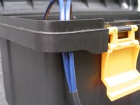
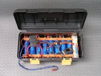
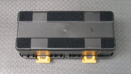
I located some Pep Boys tool boxes that were precisely the right depth and width for an 8s3p Headway pack but were a little long. These are big enough to allow all the cell configurations of interest. I use a couple of these with a press-fit ¼ plywood internal bottom for stiffness and a simple block of wood cut as a press-fit spacer for length. They have an interesting lip that allows the power leads to be run out in a fashion than minimizes water entry.

04_06opt.jpg
04_08.JPG
04_10.JPG
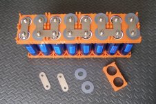
The batteries are built up using the standard Headway spacers and bus bars. These fit great, go together easily, and give a remarkably rigid pack. Taking a hint from other ES posts, I used insulating washers to avoid accidental shorts on the negative battery end. These were cut from 40mil PVC rubber shower liner (Home Depot) using an OLFA CMP-1 Compass Circle Cutter. On each pack, one series bus bar is replaced with a 50A MaxiFuse.

EDIT - This MaxiFuse choice proved a poor one - see Melted Fuse Holders

The whole business of torquing the screws, etc to get tight connections without spinning the electrode contacts was annoying until I tried using a compact Milwaukee 2410-22 M12 drill/driver (non-impact) with a #3 bit and the clutch set to #1. A pack just flies together and then I re-torque the finished assembly on a #2 setting. Perfect. No contacts ever spin, and the screws have remained tight after 850 miles. I’ve rebuilt the packs into different configurations using the driver, and everything goes really quickly.

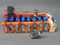
Each pack has an on-board CellLog, CellLog power switch, and balance charger connector. Old school Centronix CN-36 connectors are used. These offer large exposed wiping contact surfaces on both M/F parts that are easily inspected and cleaned as well as a 5 amp contact rating. The CellLog alarm output will run back out the balance charger cable to allow shutdown of a paralleled MW bulk charger (not in this quick build, though). See Fechter's Mini Meanwell Limiter V.3. Final packs will likely use the smaller CN-14 connectors.

04_12_iv250.jpg
04_14_iv250.jpg
04_16_iv250.jpg
The pack Anderson connectors live over the kickstand and are set up for three series packs. Currently, the center series pack is replaced with a jumper. The left connector in the image below shows four connections – the extra two are for a dedicated 12v tap – more on this later.

View attachment 6
 
Sideloaders

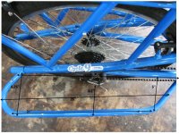
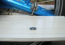
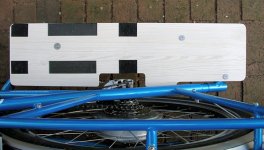
The sideloader decks need to be reasonably rigid because of the Mundo sideloader tubes only run around the outside and offer no support inside near the stays. A flexible deck tends to twist on every bump as the area near the axle moves up and down. The current temporary decks are fabricated from laminated flooring that is a sort of specialized MDF material with a plastic surface on both sides (Pergo ‘Whitehall Pine’ – Home Depot). The finish is amazingly tough (20yr!) and fits into the blue/white ocean color scheme very nicely (looks like driftwood). The width left after ripping off the tongue-and-groove edges of the flooring is 7.125”, which is perfect for the battery enclosures. Wider decks could be made by epoxying a couple of panels together.

Because it’s MDF, the deck edges and holes are sealed with epoxy so the whole thing is waterproof. I used Slow Cure 30 minute Bob Smith Industries epoxy available at hobby shops (http://www.bsi-inc.com/Pages/hobby/epoxies.html) tinted with epoxy resin pigment (white with a bit of yellow). BSI makes a good quality epoxy and you get nine ounces for under $10. The amber hardener part was tinted for an eyeball color match and then the clear base epoxy part was added to start the reaction. A fair bit of pigment is required to maintain opacity in the thin coat near the sharp top and bottom edges. The decks were positioned on small 2” high blocks and the epoxy just painted on with a small artist brush. I flipped the decks over every 30-60 minutes to even out any sag in the epoxy until it set up enough to hold in place without flowing.

05_02.JPG
The inserts on the Mundo sideloader tubes are laid out oddly and can be in slightly different locations depending on how the bike is assembled. To locate the drill points, I ran in some 5mm set screws, positioned the decks properly, and then applied pressure to the deck over the rear insert to mark the bottom of the deck with the protruding setscrew. Drilling that, I used a regular screw there, re-aligned the deck and repeated the process for the front, then middle two screws. The holes are counter-bored slightly on the bottom to clear the inserts so the decks actually rest on the sideloader tubes for uniform support. Because of the weight of the batteries and to keep the screw head profile low, I used SS flat head socket screws with washers – larger fender washers under the battery boxes (Ace Hardware).

The battery boxes are attached to the decks in an interesting way. The bottoms of the toolboxes were sanded flat to remove protruding plastic feet and then fitted with strips of ‘Industrial Strength’ Velcro – the decks got a matching Velcro treatment. The Velcro has very high shear strength and prevents the boxes from sliding around. A single strap (http://www.strapworks.com, blue polyester 2” side-release belt) secures the box vertically so the Velcro can only experience shear forces. This two part approach works very well and nothing moves at all – it’s like the boxes and decks are one...

05_04.JPG
05_06.jpg
05_08.jpg
Charging is done in place – release the strap snap catch, open the box, and plug the charger into the balance connector. Spot check state of charge by turning on the CellLog toggle.

These temporary boxes and sideloaders took slightly more time than I intended but have a pretty finished look and are rugged enough to stand up a while if Life delays the replacements...
 
Safety Stuff

Adding some safety features was an easy early decision. Over years of motorcycles and motorcycle accidents, all of my youthful confidence and schemes to swerve, veer, brake, and Do Very Smart Things have inevitably lost to the words of Joe Louis: “Everyone has a plan until they’ve been hit….”.

It seems that the best way to play in the road-sharing game is simply to appear as a normal vehicle and require the very least possible special treatment by other drivers. So, I decided to go ‘motorcycle standard’ and add a dash of ‘bicycle’...
  • I wanted powerful turn signals for safety and general driving courtesy.
  • I don’t really plan to ride at night, but twilight-just-a-little-behind-schedule riding is not uncommon, so headlight and tail light were a simple choice. Here I saw no particular reason to play with battery-powered bicycle lights – just go 12v and get regular motor vehicle parts.
  • Next I wanted the most valuable piece of motorcycle safety gear – the horn. I went with a FIAM Freeway Blaster auto horn – one of the loudest non-air-horns available. The horn is to awaken unconscious offending drivers who wander into my path, pull out, and do other life-threatening things that need their (not my) action to correct…
  • And finally, as a concession to actually being a bicycle and an obstacle to traffic, I wanted daytime Blinkys – both rear for passers and front to minimize being cut off (a constant source of sudden death). Blinkys are a great idea, but there is no reason to play with toy LEDs and little batteries – I want 12v you-can-see-me-for-100-yards-in-bright-sunlight mega-blasters.
All this safety gear certainly risks pushing the bicycle dork factor to new heights, but I have tried to go with a mixture of retro parts that will seem somehow familiar and will elicit a smile. Regardless, live dorky guys get more dates than dead cool guys… ;)

Electrical Panel

An unfortunate side effect of this extra gear is a lot of ‘glue’ parts to hang it all together - more messy wiring and stuff. I need a 12v DC/DC converter as well as a horn relay and a system relay to take the startup surge on the DC/DC converter (basically the same pre-charge issue as controllers). With lots of parts and wires, come fuses.

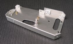
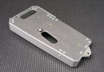
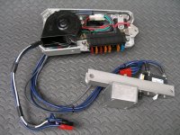
To hold all this stuff, the bike has an electrical panel mounted under the seat stays in front of the rear fender. The converter and relays fit in between the stays and the horn, fuse block, and CA-SA shunt live under the panel. A short skirt around the bottom of the panel hides the wiring mess to tidy up appearances. The panel is fabbed from 1/8” aluminum plate and the misc little bits are cut from hardware store 1/8” aluminum extruded bar and angle stock. Everything is pop-riveted together and a few rivnuts provide mounting points. To mount the panel, a single rivnut was added to the bottom of the top tube butt end where it intersects the seat stays – the other end of the panel is mounted using a couple of the many unused Mundo inserts.

06_02.JPG
06_04_iv250.jpg
06_06_iv250.jpg
06_08_iv250.jpg
06_10_iv250.jpg

To get a little extra power capacity margin, the 45A rated CA-SA shunt is sanded flat and clamped to the underside of the plate (see above). This shunt is shared by both motors.

The horn relay (eBay – ‘auto relay 12v’) is run conventionally from the handlebar horn button. Since car horns of this type are just giant interrupting inductors, the electrical noise spikes are beyond huge. Rather than overspec’ing the DC/DC converter by 6A for an occasional frantic blast and trying to suppress the electrical noise, the horn uses dedicated (+/-) lines to the battery so the rest of the bike is unaffected. A 1N4006 diode is soldered across the horn terminals as a snubber.

The keyswitch that runs the handlebar Kill switch also runs a system relay to power the DC/DC converter (Green Galaxy 36-72v 10A 13.5v 120W – from ThunderStruck Motors http://www.thunderstruck-ev.com ). This lets the key disable both the controllers and all 12v accessories. Throwing the breaker has the same effect. Alternatively, the system relay could be eliminated and the converter instead hooked up to the breaker with the controllers; the pre-charge button would then also remedy the converter startup surge issue. In that case the keyswitch would just enable the controller logic. (Of course, another option is to find a keyswitch that can directly handle a 7A current and start-up surge ;) )

The system relay is a 4-pin 48v Asian automotive style 804-1A-C1 48VDC with 7.5A 48VDC contacts with the same form factor as this 12v unit: http://www.songchuan.com/en/product_dtl.aspx?cid=_00000001&ccid=_00000008&id=_00000071 . I found it supplied as part of a golf cart lighting conversion kit on eBay but you can buy just the relay via PayPal from: Edgewater Custom Golf Carts, Orlando FL 407-402-1040 (ask for ‘Mike’). I have run this at 20s2p (66v) with no problems. The relay will accept standard spade connectors but the same relay can be found on eBay in 12v form with a nice socket (eBay ‘804-1A-C1 12VDC RELAY’). I found one, messaged the seller, and arranged a PayPal purchase of a socket alone. Or -- buy two 12v relay/sockets, use one relay/socket for the horn, use the second socket for the 48v system relay, and keep the extra 12v relay as a spare.

EDIT - The system relay and DC/DC converter wiring are shown in this later post..

Because space is at a premium, I cut the tabs off the relays and stuck them down with Industrial Strength Velcro. I slid the coil contacts out of the relay sockets and soldered a 1N4006 snubber diode across the contacts, then clicked the contacts back into place. Be careful of polarity when wiring up the relays once they have snubbers!

To keep as much of the bike operational as possible in case of a problem, the fuse block has more fuses than minimally necessary. The only real downside to extra fusing is running additional per-fuse wiring forward to the front of the bike. The fuse block (ATC/ATO 8-way Fuse Block from Arlington Products) is used to supply fused 12v Vbatt12 to the horn, fused 48v Vbatt48 to the system relay and controller logic, and fused 12v DC/DC converter power to accessories.

Oops-

As shown in the images above, the horn is bolted up to the underside of the electrical panel to tuck it out of sight. This was a major mistake, and one I am unhappy to say that I also made years ago and forgot about (Grrr). This type of interrupter horn is a big buzzer that vibrates a diaphragm. To operate properly, the body of the unit must also be free to vibrate which is why car horns are always mounted on spring steel strips. Bolted down, the body cannot move, resonance is compromised, and volume is drastically reduced. The bike horn needs to be re-mounted on a rubber disk or spring steel arm. However, as a quick fix I just loosened up the retaining Nylock so the horn is a little loose and it works about 95% which is still hugely loud.
 
Lighting

All the lighting is 12v and powered by the DC/DC converter. The components are all third party generic replacement parts for motorcycle or truck use and are wired for isolated operation without frame grounds.

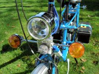
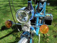
  • The headlight is a generic motorcycle light with a 55W H4 halogen bulb (Google – ‘Motorcycle Bobber Headlight 4’). These are available in both bullet and teardrop forms but the bullet shape offers more interior room for stashing other electrical parts. The small incandescent daytime running light is removed leaving just the H4 high and low beams.
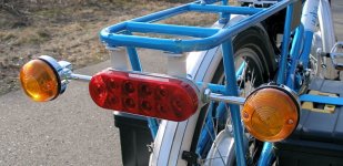
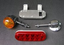
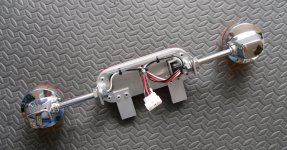
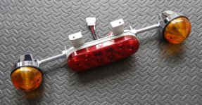
  • The tail light is a 6” Oval Optronics STL72RK Tail/Turn/Stop LED truck light that normally flush mounts with a rubber grommet. The grommet is not used and the sealed LED unit is surface mounted to save space.

    To eliminate a separate switch, a two diode isolator drives the tail light element when either the high or low headlight beams are ON. A 3-pin female JST connector is wired HighBeam/TailLight/LowBeam and a small removable isolator is made with two 3A 1N5400 diodes soldered to the pins of the mating male JST connector with the common cathodes on the middle tail light pin. Sheathed in heatshrink, the isolator just stuffed under the dashboard.

    The 10 LED brake light element is strobed as an Extreme Blinky instead of used as a brake light. It uses a per-LED reflector system that makes the LEDs appear large and extremely bright.
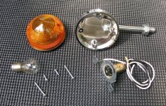
  • For sheer brightness, the turn signals are 23W incandescent reproductions of the classic 60’s Lucas lights found on Triumphs, Nortons, etc. These can be obtained from many sources including eBay and come in two lengths – I use the short stalks in back and long stalks in front so the overall width is roughly the same front and rear. It’s necessary to get a fair distance between the signals so the direction is unambiguous at a distance, and these retro lights from a time of more basic cycle frames work out nicely. The domed style and omni-directional incandescent bulb give good side visibility.
  • A single round 2” truck side light with clear lens and 4 amber LEDs is used as the front Extreme Blinky. It’s mounted in the center as a medallion under the headlight. I tried a variety of round 2” and 2.5” lights with varying number of LEDs and found the brightest by far to be a 4 LED no-name Chinese unit with bright LEDS and per-LED molded lenses (eBay – ‘2" Round CLEAR LENS Amber LED Trailer Truck’ by member RandPcarriages). This light is strobed in parallel with the brake light.
The turn signals are driven with an automobile 3-pin flasher relay. These are available from many sources including eBay – I used one with LED capability (CF13 JL-02) to leave the door open for future upgrades. The wiring is standard and can be Googled – the only minor twist is the use of a single 12v LED indicator on the dash instead of the normal two (L/R). A small diode isolator similar to that used for the tail light but using 1A 1N4001’s drives the dash light from the L/R signals. The flasher relay is tucked into the headlight housing although the fit is too tight to use a socket – standard spade connectors are used instead. EDIT - A piezo beeper was added later. See this post.

LED strobing is provided by an ‘LSC-100B Continuous Pulsing Strobe Module’ from SuperBrightLEDs (http://www.superbrightleds.com/ ) that flashes 4 times quickly, pauses, and then repeats. The module is tucked inside the headlight housing and is enabled by a toggle on the dashboard. Price is about $5 and the module is very small (think: pack of gum). I have the module wired ON all the time (tiny current draw) and switch the blinkys from the output. This leaves the option of using the same module to drive additional switches/LEDs (side blinkys, etc)

Harness wiring from the two front turn signals, strobe medallion, and tail light isolator is split out in the dashboard and run back to drive the tail light assembly.

With the exception of the reproduction turn signals, all lights came with isolated ground wires. The turn signals were disassembled and modified for 2-wire operation by soldering a ground lead to the bulb socket and using a Dremel with round burr bit to grind away the conductive plating surrounding the two socket mounting bosses - this left the mounting faces square and untouched.

07_02opt.jpg
07_04opt.jpg
Rear Tail Light Assembly

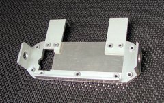
The tail light assembly is fabricated from 1/8” 5052-T6 aluminum plate and misc bits of 1/8” extruded 1/2x1/2”, 1x1”, and 2x2” angle. The assembly is pop-riveted together. The LED light unit is mounted to the face plate with 3M automotive emblem tape (auto stores, etc - used to mount emblems and trim on car bodies forever). Although the rivet heads are recessed for a tidier appearance, they could have simply been set normally and the LED unit mounted using thicker double-sided tape that would clear the rivet heads.

Like the controllers, the assembly is hung from the bottom of the luggage rack inserts with 5mm SS socket head screws. The rigid 1/8” components and the nice square Mundo inserts give a very strong mount without the need for other bracing. If this assembly takes a hit, something is going to bend or break – guaranteed – adding extra bracing will not prevent damage, just change where it happens… (Be a willow, not an oak…).

View attachment 9
View attachment 8
07_10opt.jpg
07_12opt.jpg
07_14.JPG
07_16.JPG
Front Light Pod

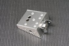
All front lights are mounted on a small custom box or pod with an angled front face that orients the strobe medallion perpendicular to the ground to shine directly into the eyes of oncoming drivers ;) The pod is fabbed in two pieces from 1/8” plate and bits of 1/8” extruded aluminum angle stock; a few rivnuts allow assembly with 5mm screws. The back of the LED medallion is filled flush with epoxy putty so it can be stuck to the face with emblem tape. A cable leaves the pod through a rear opening and runs to the dashboard where it terminates in a connector.

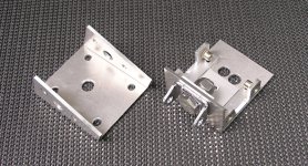
Unlike motorcycles which have bar stops, bicycles have nothing to prevent the bars from over-rotating and damaging protruding lights and other goodies. A simple solution is to mount the light pod on the head tube instead of the stem so the lights are fixed as in a car. Two SS saddle clamps (DX Engineering http://www.dxengineering.com/Products.asp?ID=14&SecID=1 ) mount the pod. Heatshrink wraps the shackle bolts and emblem tape attaches a couple of strips of 40mil PVC rubber sheet to the saddles to protect the paint.

07_18opt.jpg
07_20opt.jpg
07_22opt.jpg
07_24opt.jpg
Unfortunately, the pod is very small and was very annoying to fabricate because of internal clearance problems. If I were to do this again, I would make it larger or more likely use a small Hammond diecast aluminum box and fabricate a cylindrical wedge from epoxy putty/plastic/wood to place behind and orient the medallion strobe. Another more stealthy option is to use individual mounts to place the medallion on the head tube/stem and the turn signals on the bars.
 
Wiring Harness

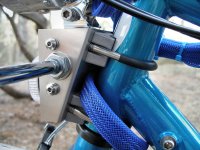
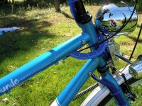
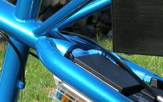
To hide the front motor phase wires, CA wiring, controller wiring, and all the accessory wiring, everything is routed through the top tube. Wiring enters the butt end of the top tube between the chain stays, snakes right and left of the seat tube (where it passes through the top tube), and exits near the head tube. The holes were drilled using a stepped Unibit. The front hole is elongated and made with two intersecting Unibit holes trimmed with a Dremel and cutoff wheel. The edges of the holes are coated with blue tinted epoxy to form a smooth built-up lip. This kind of routing is not uncommon, but I ran it by the Yuba folks first and they gave it the thumbs up. The top tube is fairly massive and I’m not doing cargo bike jumps, so the small strength compromise seems acceptable.

This feature cleans up the lines and makes the bike appear more ‘normal’, however, it did take a bit of time to implement and any harness revisions will be problematic with connectors now on the wire ends. Perhaps the biggest issue was that I needed to have all the wiring designed before I pulled the harness since additions are really not possible. A couple of extra wires and a spare 12v fused line are run forward to help out in case of future upgrades. Initial motor tests, etc were done with dangling ghetto wiring.

08_02.jpg
08_04.jpg
Front phase wiring is extended using 10ga Marine wiring (fine tinned strand) which is corrosion resistant and flexible but unfortunately has a fairly thick abrasion resistant insulation – Teflon insulated wire might have been a better choice for smaller overall diameter.

A separate shielded cable (6x24ga) from each controller brings the relevant CA and throttle connections forward to the dashboard.
  1. OUT - Throttle JST [pin 1] = +5v
  2. OUT - Throttle JST [pin 2] + Drainbrain JST [pin 2] + Shield = Gnd
  3. IN - Throttle JST [pin 3] = Throttle Sense
  4. IN - Drainbrain JST [pin 5] = Throttle override
  5. IN - Throttle JST [pin 5] = Enable controller logic
  6. XX - Spare

08_06.jpg

The stock CA shunt sense lead (refitted with JST connectors) runs from the electrical panel forward. All other loose wiring for accessories and such are bundled together and routed forward in a woven cable sheath. To reduce flex stress from turning the bars, all wiring leaving the top tube makes a loose turn around the head tube before being tied down to the stem or fork. The ‘UV Blue’ braided cable sleeves as well as colored tie wraps came from FrozenCpu ( http://www.frozencpu.com see: ‘DIY/Mod Parts’).

Although it looks like there are several blue sheathed cable bundles exiting near the head tube, only one sheath runs all the way through for loose individual wires. The other sheaths are just tucked into the opening an inch and then run up to the dashboard or down to the front motor. The cable bundles are tie wrapped together where they exit the top tube to increase rigidity for a few inches to minimize flex and chafing where they pass into the tube. Although I started out with custom rubber grommets for the tube holes, they were abandoned when wire bulk grew to fill all available space…

In the midsection, controller and power wiring runs along the front face of the rear fender from controllers to electrical panel to kickstand. It’s in plain view, but is short and seems pretty unobtrusive.

Everything is ‘connectorized’ for maintenance which adds to the construction time but is worth the effort. All handlebar assemblies and other components can be individually removed except for the in-frame harness itself and the electrical panel/controller breaker panel that must be removed together as a pair.
 
Dashboard

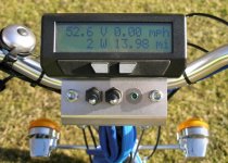
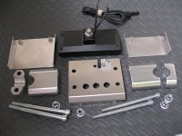
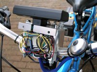
The wiring from handlebar switches and front lighting run as separate sheathed cables with connectors to the dashboard where they get plugged together with the frame harness. This makes all the individual parts removable at the cost of a pretty big ugly blob of wiring and connectors. The dashboard mounts a couple of switches and the CA, and mostly serves to hide the wiring snarl. It’s formed from a 1/8” aluminum plate mounted on upside down aluminum handlebar risers (eBay 'HANDLEBAR RISER XR50 CRF50'). There is a slot to allow the CA and wiring to be removed from the dash and a small alignment plate that prevents the CA from rotating on its single mounting bolt and shearing off the wiring. The front and rear wiring covers are 18ga aluminum sheet fitted with rivnuts.

The dash controls left to right are ‘enable strobes’, ‘select primary motor’ (front/rear), and turn signal indicator.

09_02_iv250.jpg
09_04_iv250.jpg
09_06_iv250.jpg
09_08_iv250.jpg
All CA cables have been cut down to around 4-6” and fitted with JST connectors. An additional short cable is added to bring out lines for current limiting (see below).

Handlebar Switches and Controls

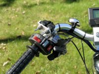
The bars are a little crowded with controls, but everything is within thumb reach and can be easily controlled without releasing the grips. (Well, except for the pedestrian bell…)

View attachment 5
An off-the-shelf motorcycle style switch assembly controls the lights and horn. I looked at quite a few but decided on the K&S Technologies 9-pin Handlebar Switch (12-0055CN). Although it has plastic body, it has good quality internal switches. It looks good, seems rugged, and works smoothly. It’s narrow to avoid crowding the bars but does have a fairly large diameter which does not play nicely with the index shifter if you want all the many thumb controls in reach. I needed to shim the switch with a turn of 40mil PV rubber sheet to get a solid mount on the 7/8” bar. The headlight switch is rated at 6A which lets it run a 55W halogen light without a relay. It comes with a plastic wire sheath and a mating connector. I didn’t particularly care for the plastic sheath, so I popped the pins from the connector, re-sheathed it with a more flexible braided sleeve, and inserted the connector pins back into the shell.

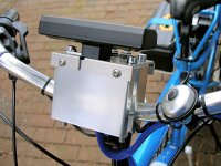
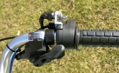
The left motor controls are mounted using a couple of aluminum riser parts (same as dashboard risers) and a custom bracket fabbed from 1/8” 1x2” aluminum angle. A few bits of aluminum tubing, 1/16" angle, and SS hardware form a stubby jack bar to relocate the index shifter so its levers protrude around the lighting/horn switch assembly. Although they are not visible in the images, there are a couple of 1/16” rolled pins driven into the stub bar under the washers to pin it to the bracket and prevent it from rotating when the shifter is used.

Actually, after some riding experience, I realize that I could have just removed the front shifter and derailleur making the bike a 7-speed – I never use the front shifter... This would have saved fabricating the jack bar.

The two toggle switches right to left are ‘enable the secondary motor’ and ‘disable CA current limiting’ (Boost!). The Boost switch is seldom used and so is placed out of the way with the longest reach.
EDIT - The left controls were reworked for CA v3 and to avoid switching controllers on/off. See post.

09_12_iv250.jpg
09_14_iv250.jpg
09_16_iv250.jpg
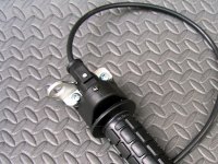
The only additional right control is a Kill switch for both motors that is attached to the Magura throttle with a bracket fabbed from 1/8” 1x1 aluminum angle. The top shift lever is trimmed a bit to clear the Magura body.

09_18_iv250.jpg
09_20_iv250.jpg
A couple of the thumb and dash toggles are DPDT (more on this later) although they appear in the above images as all SPST. For compact mounting, a good choice for these is something like the 7201TZQE DPDT ON-ON toggle which has a full size handle but a miniature body. The full size handle is rugged and easily manipulated with gloves (see this post for a comparison pic of these switches). I lucked into a handful inexpensively on eBay but they are available from Mouser, etc as standard items. All the toggles are fitted with silicone boots. Be careful when buying boots to get the proper threading: the old universal 15/32-32” switch threading has been partially replaced by M12.

And finally, owing to many decades of motorcycle muscle memory, the cables are interchanged to put the front brake in the standard motorcycle position on the right (where it belongs ;) ). Ebrakes and cruise control are not used.
 
Throttle and Dual Motor Control

The bike is set up with a single Magura throttle to control both motors plus some switches to allow on-the-fly selection of either or both motors. The dual controller hookup is done in the most obvious way using Schottky isolators for 5v sharing and controller throttle inputs. Although much has been made in the forum of the problems with a common throttle, the old school brainless Xlyte analog controllers do not have the temperamental issues of microprocessor controllers. The single throttle works smoothly and predictably at all speeds driving either or both motors. There have been no issues at all, even with a combined 3kW draw for both motors.

Since the same motors are used front and rear and are not powerful enough to spin the wheels (except the front a bit on a hard dead start – not recommended anyway), there is no slippage regardless of acceleration/deceleration weight transfer. It’s not unreasonable to view the motors, wheels, and road as a single geared-together assembly. As such, the motors share the load roughly equally and no special magic is necessary to play with percentage throttle/power splitting. Similar power use by each motor yields a similar voltage rise in both the controller Gnd rails (due to wiring resistance) so both throttle inputs see the same throttle voltage. In short, simple electronics, identical motors/tires/wheels, equal length non-shared controller power wiring, and a low powered bike with fat grabby tires simplify the shared throttle problem to allow a very workable and trivial solution (2WD Grin!).

Initially the bike had simple ‘enable front’ and ‘enable rear’ switches on the dash. After very little riding, it became clear that the rear motor was always in use and releasing the grip to switch the front on and off was pretty inconvenient. This was revised to the current setup where a single dash switch selects the primary motor; this setting typically only gets changed in case of a failure. A single thumb toggle enables and disables the ‘other’ motor, whichever that is. This is a lot like shifting and is very easy and intuitive. The functionality is achieved with switching of the controller ‘logic enable’ lines after the Kill switch. In normal use, I just flip on the secondary (front) motor to climb hills, and if necessary, then flip on the boost. Simple. If running with the front motor as the primary instead, thumb control operation is identical.

A little twist on ‘one or two motor’ switching is the desire to have CA current limiting for each but using a single CA and CA-SA shunt. Here identical front and rear motors with identical throttle levels allow another simple solution. The CA input allowing current limiting is wired up to the handlebar switches to allow either 50% or 100% limiting depending on the ‘enable secondary motor’ switch setting. With the CA ‘Max Amps’ configured appropriately for two motors (1700W), we tacitly assume that the identical motors with identical wheels/tires will more or less get half – or close enough for our purposes. Switching to one motor drops the limit to 50% or 850W.

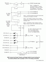
Here’s the wiring to make this stuff work - the notes show how the CA setup menu adjustments are made.

controls2a.gif
How It Works

The CA ‘Vi’ input must be configured to limit ‘Current’ in the Setup Menu (Aux Volt Functions).

The ‘Vi’ input then controls current limiting of 0-100% over a 3v range. The CA ‘Aux Threshold’ menu setting has the effect of sliding this 3v monitoring range up and down in the 5v Gnd to Vcc range. For single motor operation the junction of two equal resistors R1 and R2 is nominally (Vcc-SchottkyVforward)/2 or about 2.4v . ‘Aux Threshold’ is then adjusted to raise the baseline voltage for the Vi 3v monitoring range such that the 50% midpoint of that range (1.5v) coincides with the voltage at the R1 and R2 junction (2.4v). ‘Aux Threshold’ should nominally be (2.4v – 1.5v) or 0.9v . Variations in R1,R2 and personal preferences may push this value up or down a trifle. The exact values of R1 and R2 are not important as long as they are roughly the same and greater than about 2.2K (because of the CA 5V limitation of 5ma – in case both controllers are unplugged).

Engaging S4 (Enable Secondary Motor) shorts R1 bringing Vi to approximately 4.8v, well above the top of the 3v monitoring range (nominally 0.9v + 3.0v = 3.9v). This ensures that limiting will go to 100% for dual motor operation.

Since the CA limiting mechanism deals only with percentages, operation is unaffected by the ‘Max Amps’ setting. This means that once ‘Aux Threshold’ is set for a particular R1/R2, CA ‘Max Amps’ can be readjusted as desired and the one/two motor 50/100% split will continue to work properly.

These few parts and stubby interconnecting cables are built on a tiny electronics board that is tucked under the rear dashboard cover.

EDIT: It seems there may be a significant difficulty with the motor control portion of this design.
See: Houston - We Have a Problem...
 
Shooo weee!

I'm overwhelmed. Hard to say what was a nicer job, the build itself or the thread documenting it. Really first class work on both. That bike turned out so nice, hard to put a dollar value on your time and effort, but it's got to be many thousands.

Thanks for doing such a great job on the build documentation. Lots of really good ideas there, and well implemented. Very worthwhile to imitate them.
 
Impeccable!

I like the battery/tool boxs. Most people would assume that they contain.....tools.
 
I seen this thread last night and I am glad I waited until this morning to read and thoroughly enjoy it.

If this is your first build I can't wait to see your second. Heck I hope that by my fifth it looks part of how well
this one does not to mention all the thought put into it.

I love your aluminum handiwork also. Do you need anything special to do that ? It almost seems like something
I could do with a few new tools and some research on the how-to. Great way to hide all those wires and give it
that professional look.

Thanks for taking the time to document so well. This gives me a lot of good ideas for what I plan on doing and I
am sure others can benefit from your hard work. Looks most excellent.

Look forward to what you do with the batteries. Myself I plan on placing my batteries somewhere similar , but I
also want to use that rear area to double my kids around for short trips.
 
Thanks for all the kind words - much appreciated.

I'm a little tied up with other matters for a bit, so bear with me if answers don't get back PDQ...

dogman - I have read your posts about low speed trail riding with great interest. Living here in the Land of Hills, and having always liked the Nature part of biking (not to be confused with bicycling) for the experience and not the adrenaline, your posts struck a chord. Hope you saw a little of that in this build :wink: .

ohzee said:
I love your aluminum handiwork also. Do you need anything special to do that ? It almost seems like something I could do with a few new tools and some research on the how-to.
I will add a post about the tools and stuff. This was built using common woodworking hand and power tools except for a couple of relatively inexpensive specialty items - no metal brake, no milling, etc. But whether you use the same techniques or not, the aluminum used here is very easy to work.

Alan B said:
What are the before and after weights?
I believe the V4 Mundo weighs in at about 47.5lbs (plain vanilla, Vbrakes).

I've been doing battery experiments this winter so the bike was recently built up with 16s3p (52v30Ah) and weighs in at 48.5/98.2lbs front/rear or 146.7lbs total. Sixteen 38120 Headways at 500gr each weigh 17.6lbs so the friendlier 16s2p configuration would weigh 48.5/80.6lbs or 129.1 total. Working that calculation again a couple of times gets a no-battery weight of 93.9 (which includes the enclosures, pack wiring, bus bars, CellLogs, and other tiny bits) so call it maybe 92lbs. This accounts for the frame, balloon tires with heavy duty rims and tubes, motors, controllers, and the rest of build-specific stuff. From that you can add the battery technology of choice to do some 'What ifs'...
 
This is absolutely fantastic! I am personally just starting a yuba build. Only a single motor, but mid drive, and a V3.3. I do however love the look of yours, and love the lighting. I will directly copy a number of ideas from you if that is ok.. Also, a post on tools etc for the aluminum fabrication would be fantastic. I am going to read through this again in detail and take notes soon!

Thank you!
 
inkeeper77 said:
... I am personally just starting a yuba build. Only a single motor, but mid drive, and a V3.3. I do however love the look of yours, and love the lighting. I will directly copy a number of ideas from you if that is ok...
Many thanks for the kind words... As for the rest - this 1953 song by mathematician/songwriter/satirist Tom Leher has always served me well. I encourage you to embrace its valuable message: "Lobachevsky!".

:D

Seriously, though - I've tried to put in enough detail to make it easy to reuse any small bit or piece that can help move your build along.
 
Awesome! Thanks! I will be anxiously awaiting your post on tools and such for the aluminum part creation- I will probably follow it word for word.

I also have couple further questions if you do not mind-
1) Could you possibly give details on the keyswitch you use? It looks fantastic, and I want to know where you bought something like that..
2) Lighting system: How much of a power draw are you seeing? Mine is going to be fairly low power onboard, perhaps with more capacity for range to be added later, but currently only about 9.8 Ah. (nice a123 m1a batteries though!) I am thinking of running turn signals, a front and rear blinky, and a headlight like yours. (I like the high/low capability on a lot of those halogens..) but I am worried I might run into power issues, and should stick with fully LED.
 
inkeeper77 said:
1) Could you possibly give details on the keyswitch you use? It looks fantastic, and I want to know where you bought something like that...
eBay. That particular switch was NOS (New Old Stock) exterior grade for a security system, but switches with the same basic features are almost always available < $10 (I see some today for about $5). 52v DC can be hard on anything with contacts because of arcing, which is why I went with a relay to switch the DC/DC converter; the 'controller enable' power is inconsequential.

inkeeper77 said:
2) Lighting system: How much of a power draw are you seeing? Mine is going to be fairly low power onboard, perhaps with more capacity for range to be added later, but currently only about 9.8 Ah. (nice a123 m1a batteries though!) I am thinking of running turn signals, a front and rear blinky, and a headlight like yours. (I like the high/low capability on a lot of those halogens..) but I am worried I might run into power issues, and should stick with fully LED.
The accessories run parallel to the CA shunt so it doesn't get confused when current-limiting the motors. I unplugged the DC/DC converter fuse and plugged in an analog ammeter to measure the lights:

  • Don't worry about the Blinkys (<1A @ 12v so inconsequential on the 52v side of the converter).
  • The turn signals are 23W each or about 46W for two, but they're not on much so cause a negligible net energy drain.
  • Low Beam is approx 1.2A@52v or 62W
  • High beam is approx 1.4A@52v or 72W
The headlight readings (62/72W)@52v don't seem unreasonable for an H4 rated (55/65W)@12v considering some converter losses, etc. A 45 minute ride home on low beams would cost 62W*(45/60) = 46Wh. Running 16s2p Headway at 80% DOD I have an effective 850Wh so the H4 bulb seems okay at ~5.5% net power, particularly for only occasional use. Your situation may be different.

Here's a thread you may find interesting: Nice bike light on ebay 24-90V 12w 29.99U$ (doesn't have the retro look, though :wink: )
 
Really beautiful !

Its so clean and functional.

Thats why its so beautiful.

I wish they were for sale at the local store, because i would buy one.if they would take my car in trade and we had a nice trailer...


is that your next project to make it a true SUV ?

Thankyou good clean project and post.
 
motorino magnet said:
...if they would take my car in trade and we had a nice trailer...
is that your next project to make it a true SUV ?
Glad you like it :wink:
Funny you should mention that - I'm in the middle of a bike carrier build so I can visit more remote bike paths and such. That will make a modest battery size more attractive since I won't have to first bike to the fun part. I drive a turbo Volvo wagon that doesn't have much ground clearance so the carrier has a built-in 6" riser and is fabbed from an aluminum motorcycle carrier. Hopefully more on this before too long. So, I'm sort of using my car to support the bike habit.
 
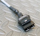
Crystalyte 12 MOSFET Controller 6 Pin Throttle Pinout

I had to scope this one out, so here’s a head start on this detail:
Looking at the connector pins, retainer catch on top, pins numbered left to right:

  1. (OUT) +5v
  2. (OUT) Gnd
  3. (IN) Throttle Sense
  4. (OUT) switched Vbatt for LED indicator etc
  5. (IN) switched Vbatt to activate controller logic (tied to pin 4 inside controller)
  6. (OUT) unswitched Vbatt (connect to pin 5 to activate CA + controller logic)
  • Pins 1-4 are as in the old 4 pin connector.
  • New pin 5 is tied inside controller to old pin 4 and Cycle Analyst connector pin 1 (red – Vbatt). Since pins 4 & 5 are tied together, they may be used interchangeably.
  • New pin 6 supplies unswitched Vbatt directly from controller PowerPole connector to activate controller logic and Cycle Analyst when shorted to pin 5.
  • Logic power leads from pins 4,5,6 terminate on a two pin connector with green wires accessible on the PCB edge directly under the blank controller end plate.
I do not use pin 6 but rather pull a Vbatt lead from the switched side of the keyswitch and use this to run to the kill switch etc and eventually back to pin 5 of the throttle JSTs.

Crystalyte Controller to BMC Motor Phase Wiring

Xlyte/BMC hookups can be found in several places on ES and the web, however, I noticed that in all cases the phase wiring actually did not alter the phase (color) order of the controller and motor, it simply introduced an offset or shift in the phases. The following table shows an equivalent mapping that does not require a phase wire color mismatch – just a bit easier to hook up. The Xlyte controller fwd/rev switch works properly (kind of meaningless in this application, but…). The 36 possible phase/sensor combinations and equivalent solutions are discussed in other threads on ES – this is just an example of such an equivalent combination.

View attachment 1
Cycle Analyst Stand Alone Shunt

The CA-SA shunt has two red/black pairs of large gauge wire 'from Batt', 'to Controller'. There is also a cable that runs to the CA proper to provide power and current sense. However, it was useful in this build to wire the shunt slightly differently to accommodate parts placement and the desire to run the controller logic, CA, and DC/DC converter separately using a keyswitch.


Strictly speaking, it isn't really necessary to run the main (+) battery power through the shunt dongle. On the bike, the switched Vbatt48 power from the keyswitch is routed to the CA-SA shunt Batt+ connection to enable the CA using 22ga wire, but the heavier 10ga primary battery (+) wire takes a more direct route to the breaker and then controllers. The CA-SA shunt Controller+ wire can be left disconnected or used as a pass through tie point for the keyswitch Vbatt power. Only the negative controller power actually passes through the dongle.

EDIT - The shunt wiring is shown in this later post.
 
Project Checkpoint - Quickie Assessment

Since it's spring and time for builds to start, here's some thoughts on how well this has worked out so far. Some points were already mentioned, but here it all is in one place:

  • In general - I couldn't be happier - this thing is super fun, climbs hills like crazy, and has gotten me home without problem even with a major controller failure.
  • This is a heavy sucker, but simply treating it as a lightweight motorcycle instead of a bicycle gets all the expectation out of your head about picking it up to move it - you just do things a little differently to turn it around, etc. And of course, regular car bike racks are out of the question.
  • Roadside tire repair is possible for the rear wheel, but the derailleur, batteries, sideloaders, hub motor, and torque arm make it so troublesome as to be avoided at all costs. Preventative strategies seem the better plan - heavy duty tubes preloaded with Slime and probably periodic tube replacement depending on mileage (annual pre-season?).
  • I'm happy to have the turn signals pretty much on a daily basis - beyond the safety aspect, they seem to elicit a fair bit of driver courtesy...
  • I've used the halogen headlight in the twilight but not at night. I'm glad it was included but it was used in the dusk more as a signal than for illumination. Considering my particular needs, a more powerful front Blinky would have worked as well.
  • The Blinkys have been a spectacular success - these are really worth the small trouble to implement. I can see drivers focused on the lights when they approach from behind and I seem to get a wider passing berth than other bicycles that are on the same roadway. From the front, I can again see drivers eyes locked onto the front of the bike and seem to benefit from extra long delays on their part as I approach and pass side-road pull-out situations. I think this may in part be the 'What the ... ?' factor, but I'll take it anyway :). Regardless of how they are implemented, these seem worth considering.
  • The front Blinky was chosen to be less obtrusive and to fit into a geometry/design I had in mind. However, it is nowhere near as dazzling as the rear unit. Next build I will probably use the amber counterpart of the rear light, a 6" oval Optronics STL 72AB turn signal. This could be mounted up with short stalk turn signals as in the rear, or even mounted vertically on the head tube if the turn signals get hung from the bars.
  • I have used the car horn exactly once to stop an SUV back-out pull-out. Worked great, but this one is like religion - a personal choice that's not too good to argue about...
  • The particular fuse block I used is itself very rugged and well built and won't need to get opened much (I hope), but the cover is a little annoying to get on and off. It is made of some very tough plastic but I am none the less always afraid of breaking it when I open it (it's just me). I removed a little plastic stop so it could be installed either way instead of having a specific top and bottom.
  • The jury is still out on the Headways. They work super, got me on the road quickly, and simple enclosures are pretty easy, but the large cell form factor can be a little problematic when trying to squeeze the most power into odd shaped spaces like the Mundo sideloaders. They seem a pretty fair choice for the 16s2p configuration, but things look a little more dicey going for more. Next build phase will address this directly. For a modest Wh rating, something like Kiwi's full in-frame solution would be preferable when he gets his batteries and boxes in production.
  • The 2A VoltPhreaks balance charger (post coming soon) has worked out well - no BMS issues, cells are balanced perfectly every trip. The obvious downside is the charge time. I get one ride a day for 1.5 - 2 hours which is pretty acceptable. If you are building up the battery from LiFePO4 cells, this seems a simple way to get going and then add a bulk charger later as needed. Unfortunately, there may be an issue with the way I packaged the chargers - see the Balance Charger post.
  • The front torque arm has not loosened or moved a whit. T-bar clamps are extremely robust and seem worthy of consideration for other torque arm situations. Also, Kiwi has mentioned that he will have a custom Mundo front torque arm available soon. His designs are slick - worth looking into.
  • The rear torque arm is equally problem-free, but now that they are available, I would recommend using Kiwi's custom torque plates as a simpler and cheaper solution.
    EDIT: Dishing of the washers inside the dropouts was detected - see Dropout Washer Dishing.
  • The left side of the bar is a little crowded and it took a bit of extra effort to get the shifters integrated for easy use. In retrospect, I think I would simply remove the front derailleur and run the large chainring as a 7 speed to simplify the build and remove some clutter (enhancement by deletion is always attractive...). In the very unlikely event of actually needing to pedal this monster, it's simple to manually hop the chain to another chainring as an emergency fix.
  • As mentioned earlier, the breaker for protection and as a main disconnect is a huge success. It is, however, not rated as weatherproof although this doesn't seem to stop exposed installations on small pleasure boats. I skirted the issue by mounting it upside down to discourage water entry - there is no means to screw on a conventional toggle switch boot. If you want extreme waterproofing, you may want to look elsewhere.
  • I am not happy with the MaxiFuse pack protection. It was easy to implement but they are only 32v fuses in a 52v rig, and they are huge. There a quite few posts on ES about this problem and I'm still looking....
The two motor rig turns out to be a good test platform for single motor comparisons - here's some thoughts:

  • A single BMC V2S is a great choice for a cargo bike like this. I'm sure you will be happy with the performance and a single BMC is a great hill-climber in its own right. I started out using both motors for almost all hills, but soon discovered that with assistance, a single motor handled modest hills very well - and I run the motors below Ilia's recommendation for max power limits. I can't speak to the differences between the V2T and V2S (or now V4[T,C,S]) but talk with Ilia at Ebikes SF.
  • Since I can run a single V2S motor either front or rear, I have to say that with a heavy bike and so much traction in comparison to motor power, a front motor rides very nicely. If you are looking for a simpler one motor Mundo build - the front motor solution will save you time and headaches and you will retain the 48 spoke rear wheel. I still like the rear slightly better, but I think the difference is much smaller than on a lighter, higher performance bike and traction concerns are very much reduced. The front gear motor is pretty quiet (hardly noticeable at bike path speeds) but is somewhat noisier than the rear, apparently because of the hugely rigid frame members in back.
Hope this adds a little perspective to the build choices after a bit of real world use... :wink:
 
Back
Top