Full Suspension Longtail: 20" 104V HT3525 rear and 29" front

Lemlux

100 W
Joined
Mar 21, 2011
Messages
227
pipe repair mount.jpgH-hub-20in-moped-rim.jpgfs cargo bike-b.jpgView attachment 5View attachment 4rear bb offset-3.jpgrear triangle.jpg

First, let me apologize for being unable to control which photos are inbedded, which photos require opening by the reader, and the location of these photos.

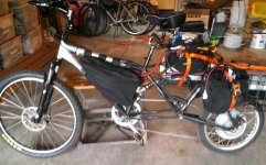
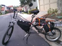
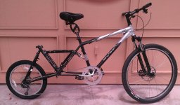
With advice from many on these forums I'm into my second build with a full suspension hubmotor cargo bike that is designed to carry my 260# 66 year old body plus cargo up and down steep omnipresent SoCal coastal hills without overheating.

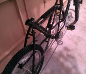
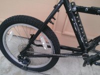
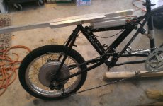
The bike is pictured as it now stands before adding electrical items, a chain drive-side idler, extending rear derailleur and brake cables etc.

Main frame is a 2007 Gary Fisher 26" Big Sur Hardtail size 19". Fork is an inexpensive but reasonably solid Rockshox XC 32TK 29er with a BB7 203mm disc brake and a 2.1" tire.

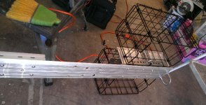
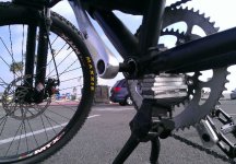
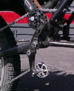
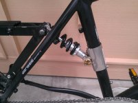
Rear triangle with down tube and top tube stubs is a fairly heavy chromoly Giant 26" ATX 770 small 16" frame from 1993. Following Spinning Magnet's lead I've connected the frames at the GF rear dropout and the Giant BB. I built up a simple threaded 10mm rod to fit a fairly standard BB so I could attach with nuts on the outside of the dropouts. I then built an adjustable reinforced strut assembly from 1/4" by 1" aluminum bars reinforced with aluminum tubing. The strut assembly connects to a spring that is removably attached to the GF seat tube with a 3" long load-spreading stainless steel pipe leak repair clamp with integrated rubber cushioning between the stainless steel and the down tube.

The strut is attached at the top to a welded-on 1/4" by 1" steel bar with holes at 1" spacings that I repurposed from unused extra mounting parts from a garage door motor assembly. I'll use one of the lower holes to mount a chain guide that eliminates chain interference with the axle mount in the GF rear dropout.

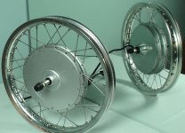
The rear wheel will have an HT3525 hub mounted into a relatively light 2.4# 16" * 1.6" alloy motorbike rim. I drop shipped the rim to Ilia Brouk at eBikesSF who did the very nice single cross lacing with Phil Woods 12 Ga spokes. I'll initially run the relatively heavy 29 oz. Subrosa Gravedigger 20" x 2.3" BMX tire in back until and unless I see the need to replace with a motorbike tire that could weigh as much as 8#. (Until I mount the HT3525 wheel I'm using an old 20" wheel with a 9 cog 11-34t freewheel that fits in the appropriately spread-out Giant rear dropout.)

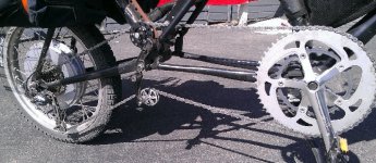
The larger chainwheel is a 60t Vuelta which required both (a) the use of a 153mm wide BB recommended by Chalo to eliminate chainwheel interference with the GF right chainstay and (b) offset-mounting the Giant 113mm wide BB all the way to the left side of the 135mm wide GF rear dropout to keep the chain from bending against the same GF chainstay.

I'll be driving the HT3525 with a Lyen 18 FET 4115 controller powered by 20 AH 32S LiFEPo4 cells which appear to be able to get me to 36mph on flat ground at WOT. Ilia is installing a POT in the 200V CA which will allow me to infinitely adjust the current below the 45A Lyen default. Regen is enabled and will be activated with the rear ebrake handle. I'll set up the Crystalyte cruise control and an on-off toggle switch for regen for use if the motor overheats going downhill.

The 104V 20AH battery pack will be built from less expensive 2A continuous load and 3A max load rated cells because the relatively higher voltage pack will pull proportionately fewer battery amps for the 2 kW to 3kW max loads I intend to use for acceleration and hill climbing. I expect to mount 8 cells in the front triangle, 8 cells below the strut in and below the GF rear triangle, and 16 cells in and around the strut assembly.

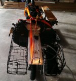
I should also be able to mount a pair of Wald foldable 12.5" long by 7.5" wide by 8.5" tall baskets over and mostly in front of the rear wheel for cargo. Heavy cargo should be accomodated with BOB Nutz mounted in the rear dropout area for my BOB trailer.

BTW, when towing the BOB trailer I believe that I qualify for riding a "3 wheeled device" up to 30 mph legally as a senior citizen pursuant to section 407 of the California Motor Vehicle Code.

Since the CA V3 beta units aren't available now I'm having Ilya set up a temp display that should mount on my 130mm stem just below the CA.

I don't think that the rear suspension should cause the main BB to drop more than 2". Since the bike is set up with both GF dropouts at 14.5" from the ground this provides 1.5" more clearance than stock for the GF. Another 30mm of clearance is provided my the 145mm crank arms instead of the stock 175mm. The short cranks should also be kind to my old arthritic knees and enable me to more easily maintain (or approach) the higher cadences required for 20-30 mph speeds with a 20' rear wheel.
 
Looks very interesting. 104V on a 20-inch wheel should be an awesome hill-climber. Also, since its a direct-drive hub, you would have the option to use regen to keep the standard bike brakes from getting too hot on a long downhill.
 
Nice looking bike mate!
Hope you have fun with it when you get it up and running :D
 
Giant Surly Dropout d.jpgThanks, guys. I do view regen more as a brake preserver than as a power regenerator.

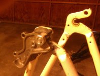
I forgot to mention how I addressed both a torque plate issue and a rear disc brake mount issue on the 1993 chromoly frame rear triangle. This pic shows the beefy 1/4" thick Giant chromoly rear dropouts with a Surly chromoly rear dropout / disc brake adapter part. I had to grind away some of the Surly part that interfered with the seatstay in order to mount it flat. I reinforced the bond with the bolt mounted to the lower left of the dropout.

After bonding the adapter I messily filled in gaps between the parts with epoxy putty.

The Surly part is 0.35" thick at the dropout which provides a combined chromoly dropout thickness of 0.60" (=0.25" + 0.35"). I'll also use a more standard torque arm on the other side and mount with Nordlock washers to help withstand alternating acceleration and regen forces.
 
I bet that rides real smooth. Interesting build, and unique.
 
ev_Bag6.jpgBattery_3.jpgBattery_2.jpgev_Bag_5.jpgev_Bag_4.jpgev_Bag_2.jpg

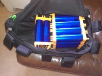
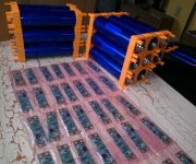
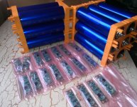
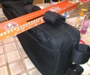
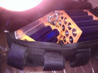
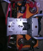
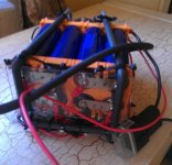
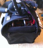
Received my Falcon-EV bag back from the upholsterer widened to accomodate a 3-wide headway pack that has already been accomodated with my 153mm wide BB. Here are pix showing the widened bag, 16@ 40152 Headway cells in the bag before I cut and attach protective sides, balance wires, balance boards, keyed battery interrupt switch, and 50A 150V DC circuit breaker also inside the bag. Other pictures show the pair of 8S subpacks that will be mounted rearward.

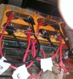
Balance Boards (GBS boards that burn off V >3.55V at 0.5A) will be mounted inside a lexan sandwich with top layer holes that will allow for easy access to either DVM measurement and single cell charging for balancing if desired.
 
hinged_aluminum_11.jpghinged_aluminum_9.jpghinged_aluminum_4.jpghinged_aluminum_8.jpg

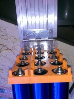
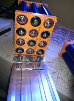
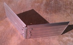
I've cut a pair of 8.5" long sections of the 5" wide aluminum door threshold and joined them with a 4" door hinge. The bottom portion accomplishes the objective of rigidly stablizing the bottom crossover from seat tube to down tube while the rising section rests firmly against the inside of the bag which touches the downtube. Other pictures show how well the aluminum width lays against the 3-wide Headway block. I've temporarily fastened the aluminum to the headway mounting blocks with 1/2" #6 machine screws with extra washers to ensure that the screws don't threaten the cells. Some of these mountings will be better secured with 3/8" screws in the fully wired final setup.
 
Lots of Pix at Bottom!

Had to remove the hinged aluminum platform from the triangle bag in order to squeeze the bag to fit into the deceptively small triangle of the 19" Gary Fisher Big Sur frame with 12S Headway cells and accompanying 12 balancing board assembly. Had to limit triangle bag to 12S Headway 15A cells for same reason due to the space taken up by 12 balancing boards mounted on triple layer polycarbonate sandwich assembly.

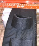
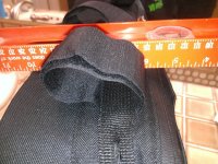
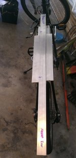
A 100A Hella marine master battery switch with removable key mounted inside a repurposed ABS Logitech 3" PC speaker enclosure along with 4S Headway cells, 4 balancing board sandwich, and 50A in-line fuse all mounted in small 8" by 11" footprint tool bag just behind seat. Bag is on top of 3' long 5- wide aluminum door threshold used as a rack and mounting platform. The master battery switch is wired between the 16S front battery segment and the 16S rear segment. Key removal eliminates all power drains, protects against power-on incidents by curious kids or worse, and totally separates the segments for charging with a pair of 48V chargers with a 57.4V shutdown.

3' long mounting platform rigidized by 1/8" thick 1.5" by 1.5" aluminum angle bolted to bottom of door threshold and to holes drilled in the Chromoly Giant seat tube and cut-off top tube. Additional platform support provided by bolt-on repurposed main aluminum member from 5 @ removable 5 1/4" wide aluminum IDE hard drive enclosures.

Prior to mounting 3' long door threshold platform the Lyen 18 FET 4115 controller was mounted on top of the upper strut arm. The platform and support hardware is mounted over (but not touching) the controller.

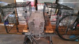
Two @ 8S headway packs with matching sandwiches for balancing boards each separately placed and heavily foam cushioned in a pair of electricians' tote bags with 8" cubed internal space. Both bags firmly mounted and protected inside tubular steel framework of 2 Rubbermaid wall-mount garden hose fixtures which, in turn, are mounted to opposite ends of a 16" section of aluminum door threshold. This 16" subassembly (which is 3-4" wider at the outside edge of the tote bags) is then bolted onto the platform over the platforms connection points on the Giant seat tube and top tube stub.

Several SST U-bolts protrude from the platform as mounting anchors to secure the rear battery packs and reinforced cantilevered extensions of the platform and 16" battery cross arm. Self Retracting Ratchet strap assemblies are mounted in such a way as to transmit bouncing forces back to the area above the Giant mounting tubes as much as I can. These straps are not pretty, but they function conveniently without loose ends for the moment.

A pair of Wald folding baskets are mounted to 4 @ of the wide sections of the repurposed hard drive enclosures aft of the battery tote bags. Although there is no bottom support structure for the baskets, the reinforced platform superstructure holds them cleanly away from the rear wheel with grocery bag loads on board.

The bike is stable enough as a commuter, and the 29 x 2.4" Maxxis Argent tire that replaces the 2.1" WTB in front provides reasonable control on the prevalent sandy topped hardpack I traverse about 5% of the time. The bike is not nimble and is tall enough that I don't attempt very slow tight turns without putting my feet down. Top speed on the flats hits exactly the 36+mph Justin's simulator predicts. I find the bike to feel considerably more stable at 29mph than at 36mph.I lucked out in that the multiple separate suspension elements (including seat springs & thudbuster) combine for a very smooth yet controlled ride on rough pavement at 30mph. I didn't really know what to expect with the spring strut assembly I built with an 800# rated spring. The strut spring hasn't bottomed yet that I've sensed. I'm thinking that moving the Maxxis 2.4" tire from the present 19mm rim to a 35mm wide rim might improve turning stability at speed at lower psi. {[edit] Increasing the front tire's pressure from 40psi to 55psi has significantly increased turning stability at 36mph with the narrow 19mm front rim. I'll not change the front wheel width in the near term.}

I do note that I need every mm of the 153mm wide bottom bracket for the widened triangle bag.

I limit the controller to 30A, although I have noted acceleration transients to about 3450 W. With minimal pedaling I can average about 20 mph at around [edit] 35-40 Watt Hours per mile. I have no problem making 35-40 mile round trips on 13-14 Ah. I'm delighted that a trip that burns 13Ah to 13.5Ah of the 15Ah pack ends with the 32S pack at a no-load voltage around 104V = 3.25V per cell ave.

The cells stay in close balance and all the red shunt 0.5A burnoff LEDs which activate at 3.55V seem to light within a 90 second window. The pair of 57.4V shut-down chargers are inclined to run for a significant time after the red LEDs light, so I try to turn the chargers off 2 minutes after the fourth of 4 Red LEDs that peek out of the small battery/switch bag turns on. [edit] With the CA on the voltage reaches 115.1V and holds for several minutes before flickering between 115.1V and 115.2V. This is now the popint where I disconnect the chargers.

The EPS chargers seems to still be charging at 6A at the time the red LEDs light up. Thus, I can plan a charging time of (Ah consumed / 6) before I need to monitor the chargers more closely. This surprises me because I had been led to expect a charging time of (1.4 * Ah consumed / 6) The charging current input slowdown apparently won't occur before reaching 3.55V per cell.

The highest voltage that the CA has reported [edit] 2 or 3 minutes off the chargers has run between 111 and 112 volts. After 24-36 hours off the charger the surface charges dissipate down to a little over 107V and drop to 106V over the next few days. 107V works out to 3.34V per cell which is what I've read that Headway cells are expected to settle to a day off of the charger

Voltage sag during the first 12Ah of consumption at 2C max draw rarely drops below 97V to 98V. The lowest I've seen is 96V. For the moment this has given me comfort to set the CA LVC at 92V.

The loaded bike is heavy and long enough that I've not come close to a wheelie. It accelerates smartly with or without pedaling hitting 3000+ watts most of the time for very brief periods before I back off the throttle after gradually applying throttle. In spite of Ilia Brouk's caution that the Lyen 72Vcontrollers seem to be a little bit less smooth than 72V Crystalyte controllers I find this 130V nominal 150V peak max Lyen controller to be very smooth generally. [edit] I suppose the smoothness is a function of running sensored.

I have a regen activation/ deactivation toggle switch that I leave off most of the time. Going down a 5% grade at 20mph regen will generate between 500W and 800W. At 30mph on a similar or greater grade regen will peak at about 1500W or 1C. The 1500W level exerts the highest drag and activation force that I would want. Ilia tuned the controller regen perfectly. I'm very happy to have the 1/4" thick chromoly dropouts with the Surly 0.35" thick chromoly dropout-disc mounting assembly held firmly in place with 2 pair of Nordlock washers provided by ShinyBalls. BTW, I needed to piggyback a second Avid BB7 160mm disc adapter on top of the first to achieve appropriate caliper / disc engagement with the Surly dropout/brake-mount plate mounted on top of the Giant dropout.

On the hilly 4.5 mile round trip to the nearest shopping center I typically achieve 8-9% regen. On a mostly flat 35 round mile trip along the coast regen typically drops to 1.6 - 2.0% as I attempt to time stoplights while coasting.

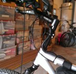
Other refinements include the use of a 700mm wide handlebar with a 2" rise mounted on a Delta stem riser that sits on top of 70mm of spacers on the uncut steerer tube. So far this extension doesn't feel flimsy although I need to lengthen the front brake cable to accommodate the additional 3.25" rise.

I'm happy to summarize that the HT3525 torque winding inside a 20.5" diameter tire with 104V has yet to noticeably overheat in my application. I don't baby it other than trying to stay between 1500 W and 2000W max while cruising, not to exceed a 1500W average while climbing, and trying to limit 3000+ W surges to acceleration spurts of <10 seconds.

Next to Do:

Replace front brake cable with longer cable to accommodate higher handlebar.

Fabricate BOB trailer hookup hardware for rear axle using Golden Motor rear axle washer with tongue and a drilled steel plate held by washer tongue. Gary at Golden Motor Canada shows this setup on his site. Driving thus far gives me confidence in pedaling this up hills with at least a 50# load in addition to loaded baskets. It will be interesting to see if this trailer setup is stable at the suggested 25 kph limit recommended by BOB.

I've already broken a single legged extended Greenfield kickstand leg that mounted to the back of the 2 left-side chainstays on the complete forward frame. The chainstay clamps are reusable and I plan to mount a double legged kickstand to a spacer that attaches to the chainstay clamp mounting platform.

Wider front rim?

angle-base.jpgangle_2_base.jpg8S_Bat_Pkg.jpgbat_frame_1.jpgbat_frame_2.jpgBat-Tote.jpgplatform_1.jpgPlatform_2.jpgBike-ready.jpgbike-ready2.jpgView attachment 1Steerer-Ext.jpg
 
Lemlux said:
First, let me apologize for being unable to control which photos are inbedded, which photos require opening by the reader, and the location of these photos.

Files <250k in size are linked. Over 250k are shown as images. >500k in size not allowed. Don't know why these sizes are set that way.
 
I think the photo size parameters are either different to what you've mentioned or have changed. Upon review recent file uploads of <100k seem to be linked while many between 100k and 200k now are imbedded. I wonder what the code really is. I wonder if different file formats have different forum rules.
 
Excellent work.

I am trying to do a longtail like this and want to know how you built that 10mm rod to sit correctly in the BB bearings. I am converting from a square taper BB, maybe yours is a different type. I tried using an old rear axle rod, but don't have the right size cones to fit the BB bearings.

Also, since the rear triangle is offset, do you have any problems with the suspension linkage twisting, or odd ride characteristics due to the rear wheel not being in line with the main bike?
 
I found the 155 long mm threaded 10 mm rod with a 20 or 25 mm unthreaded center section at a LBS. I told the owner what I was trying to do and he pulled the rod out of a box of parts designed to be used with older lower end bikes. I didn't absorb what its intended application was.

Next I used jb weld to bond about 110 mm thickness of multiple 10mm washers to the left-center of the threaded rod. I then applied more jb weld to the outside circumference of the washers. After I bought a Shimano BB with outboard bearings I then sanded down the circumference of the built-up bonded washers on the axle rod until they had an interference fit with the ID of the outboard BB bearings. These Shimano outboard bearings have a flat cylindrical ID surface at each end of the BB that appeared to be about 5/16" or so wide. These bearings support all of the weight of built up axle rod.

The BB is secured right next to the left dropout separated only by a fender washer. The right side of the BB is prevented from sliding further to the right by a machine collar. The remaining space on the threaded rod from the machine collar (which sits on top of bonded washers) to the right dropout is occupied with 10mm nuts and washers. Fortunately the rod is just long enough to hold locknuts on the outside of the dropouts.

The swing arm assembly does extend from left of center of the main double diamond frame which causes the spring to mount a little closer to the left seat stay of the main frame than to the right side.

Fortunately, I haven't been able to notice any sense of imbalance due to the rear wheel being roughly 15mm off center to the left. Perhaps I unconsciously compensate for the offset with an imperceptible change in lean angles when riding.

The off-center mounting was unavoidably necessary to provide a chain line that didn't interfere with the right chainstay of the main frame. It appears that the stability of the BB mount has thus far prevented any torsion problems on the spring strut assembly (or swing arm assembly if that's a more accurate description). Nonetheless, I think the swing arm assembly and spring are the weakest elements in the design. In summary, the relative weakness of the swing arm assembly appears to be more than compensated for with the lateral stability of the BB mount. I think this BB mount provides considerably more overall lateral stability than, say, an Extracycle Free Radical.
 
Cool, thanks for the detailed explanation.

Modifying an extra long square taper BB spindle might be an easier method. Sickbikeparts.com has really long spindles.

That 10mm rod is the rear axle from an old bike - before quick release axles came about.
 
I considered using a Sick Bike bb with spindle (I use the 153mm integrated BB & spindle from SickBike in the main BB to provide wide triangle bag and 60t chainring clearances and I recall seeing their 158mm separate spindle) but I couldn't figure out how to secure either to the outside of the dropouts. Is there a spindle length that is perfect to hold the spindle in using a washer between the dropout and the spindle-end machine screw?

If not, how would you modify the spindle to work?
 
Update on the EPS balancing boards and EPS chargers.

I forgot to turn off the master battery switch two days ago while charging and, happily, confirmed that this would not damage the CA. Better yet, I noticed that the rapid voltage steps up during the late stages of charging above 110V all but ceased and held at 115.1V, an average of 3.597 V per cell.

The chargers are supposed to turn off at 57.4V each or a total of 114.8V or 3.588 V per cell. I don't know how long I'd have to wait before they'd actually turn off.

I imagine that the discrepency between 114.8V and 115.1V is within the combined tolerances of the chargers and the measuring accuracy of the high voltage CA. In any event I am now more comfortable that the final stages of charging are constant voltage at a lower than 6A current at a level that well matches the 0.5A balancer shunt burnoff above a specced 3.55 V per cell.

When the chargers are unplugged after the CA reads 115.1V the CA reading falls below 113.6V (or 3.55 V per cell) in less than 1 minute and to around 110V (3.438 V per cell) within a few minutes and to the 107V range in about 24 hours.
 
Bike-Screen-Stand-2.jpgScreen-4.jpgView attachment 1Stand-1.jpg

I've completed two of my previously identified upgrade projects and made progress on a third.

Wider rim for 29" Maxxis Ardent 2.4" front tire:

I've had a 26mm interior width Sun Ringle 33MTX 36h rim laced into a Shimano XT rim with Sapim 13-14mm spokes. The width of the inflated Ardent casing has increased from 2.18" to 2.38" when previously mounted on my 32h Alex DH19 rim with an 18.5mm interior width.

Increased volume and width make tire much more stable turning at speed, even with inflation as low as 35psi minimum rating for tire. (35psi-65psi rated). 36mph no longer feels vaguely uncomfortable. Previously I needed to run 55psi to feel slightly less stable [Schwalbe cautions against running >55psi with a 60mm wide tire on a 17-19mm internal width rim.]


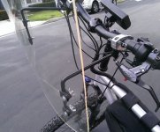
Windscreen Mount for cool 40 degree to 60 degree winter mornings.

I bought a 23" long by 18" max width screen with handle bar mounts on Ebay for about $55 delivered that was discussed on an earlier thread. I like the functionality and the fact that I can remove it by removing only two screws that pinch the two mounting rods to the handlebar mounts. I may in the future lower the screen by about 2" by reorienting the longer arms of the 80 degree bend mount rods to the parallel-to-screen position from the handlebar-to-bend position.

Pletscher 320mm dual kickstand mounted:

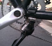
After breaking a Greenfield stay mounted stand that broke within 3 days from the bike's weight I knew that I'd have to fabricate a bottom base extension for the Pletscher mount. The longest 10mm bolt I could find at Ace Hardware would only fit a 1/2" thick bottom mount-plate pad, so I took angle grinder and drill to 2 pieces of 1/4" by 1" aluminum bar to fabricate the base.

The 1/2" extension barely works as both wheels still touch the ground, although more of the front fork stanchions are exposed due to load relief. The front fork needs to be turned to prevent extreme tippiness. For the moment I try to park on uneven surfaces with a lower front or back wheel position.

I'll try to find a longer 10mm bolt and add between 2 and 4 more 1/4" x 1" mounting base thickening laminations to the mount. With 4 laminations to the extender I'll definitely need to epoxy a stabilizing pin through the laminations into the Pletscher bottom mount. (Note from picture how use of the stand has rotated one lamination against the other.) The stabilizing pin will complicate any alternate use of the Pletscher mount unless I leave the end extending into the Pletscher head unbonded.
 
You gotta get a video of the performance..!
 
I don't have a video camera, but maybe I'll be able to find someone willing to video me off the line.

The Halls and Lyen controller allow me to creep off the line smoothly if I so choose. Even dismounted I can precisely move the bike around in my garage under throttle. It feels like Ilia at ebikesSF programmed the 1/4 turn thumb throttle logarithmically.

Since the cockpit crowds me when I'm standing (the handlebars come to just under and maybe 10" in front of my nipples) I typically start with my left foot on the left pedal at the lowest position with a light throttle. Once seated I tend to go to wot quickly (unless turning) and may or may not pedal. Acceleration is very quick up to 25 mph or so. I'll peak between 3000 W and 3600 W for 2 to 5 seconds and watch the voltage drop as I approach cruising speed of anywhere between 22mph and 30mph. I normally only go to 36mph on the flats when I want to get away from traffic on roads without bicycle lanes. This may change as I get used to the benefit of the windshield.

Cornering is much more stable with the wider rim as I said before so I get to lean far enough into turns to reminds me of my motorcycle days.

I used to be strong enough to right up a lain down 640# BMW straight 4 without much hassle -- My arthritic body now thinks my 120# ebike is more than enough to lift up. Did I say that my hips now require me to lay the bike down to mount and dismount? My next project may be a heavy duty step-thru or a semi-recumbent for that reason.
 
No videos yet.

I finally executed a couple of improvements I'd been putting off.

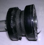
The original idler pulley on the power side was an untoothed guide. It was as chewed up as shown at about 1500 miles.

Old Idler Pulley Guide.jpg

I noticed that Utah Trikes advises that untoothed guides be used only on the slack return path of the chain. UT advises that the tension forces of the power path require a toothed pulley guide. After chewing up the untoothed pulley, I sprung for the pictured 14t titanium sprocket pulley with ceramic bearings. So far, so good. (edit: The pulley floats on a sst 8mm bolt which keeps the chain line straight. At first the pulley chattered whnever I shifted more that 2 gears quickly as the pulley Id surface slid unevenly over the 8mm bolt. A thin application of grease on the bolt was all that is now needed for a smooth lateral float.)

View attachment 2View attachment 1

I built up a 6-layer lamination of 1/4" by 1" aluminum bar base extension for the Pletscher kickstand per previous discussion. The kickstand is now stable on most ground surfaces.6-lamination Kickstand Base.jpg
 
The kickstand is already the longest 320mm Pletscher size.

The Pletscher kickstand specs a max load of 25kg (total bike weight? or weight borne by kickstand? - does anybody know?)

I feared that lengthening the legs would increase the stress on the aluminum alloy legs (and there is stress on these legs). Since I already broke a single leg Greenfield (sp?) stand on this bike, I thought I'd baby the Pletscher legs.

I like the Pletscher's range of motion as it doesn't hit the 60t chainwheel - (for perspective the smaller chainring is a 39t). I noticed that two other dual kickstands options, including a stronger steel-legged stand, interfered with the chainring.
 
A year or so ago I bought a Surly Singleater for $10 at a bike swap meet. These are normally used as chain tensioners when screwed into the threaded derailler mount. (They list for about $50 and can be found on line for about $43.) I had planned to mount it on the drive side of the chain but couldn't effectively mount it. For $10 I just put the Singleator in a parts box.

My not-so-nimble joints require me to lie the bike on its left side to mount and dismount. While doing this the chain occasionally slips off the bottom of the 60t chainring because of the long double rear triangle run to the derailleur. It finally occurred to me to mount the Singleator on the front frame's empty derailler hole both to raise the return chain and to shorten the span that is prone to falling off the chainring when the bike is on its side. I guess the only reason I hadn't previously mounted the Singleator is because of Surly's prominent warnings not to use the singleator with other than a single speed. The warning makes a lot of chainline sense if mounted the singleator right below the gear cluster but not so much if mounted below the back rear triangle's bottom bracket where it mates with the main frame's rear dropouts.

I've only ridden about 70 miles in this configuration with about a dozen mount-dismount cycles. Everything has remained in place and shifting remains smooth. I've yet to notice a problem from using a toothed idler in the return line as opposed to a grooved smooth idler.

singleator_2.jpgSingleator.jpg
 
Nicely done! I've been ignoring the pictures section way too long.

I love the idea of the full suspension longtail cargo bike, as you may well know.
 
Why high voltage for only 36mph?
 
h0tr0d said:
Why high voltage for only 36mph?

Assuming his motor tops out around 36mph, high voltage on it would mean great acceleration and efficiency.
 
Back
Top