Hi All,
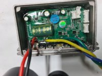
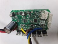
Along with about 80% of the other riders, I've had the unfortunate experience of frying the controller on my Ninebot ES2/ES4. After researching online I came to the conclusion that these boards are flawed in their design and many consumers are having to replace their control boards after as little as 3 weeks of normal use. OEM control boards (not clones) go for about $75-$100.
What seems to be triggering the board failure is use of the electric recuperative brake. If you read the reviews and forums you'll find that people are simply told not to use it or risk frying their board.
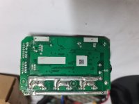
The board has weak solder traces on the back which share a common path to the MOSFETs. So luckily the traces blow long before the MOSFETs can be damaged - this means anyone with basic soldering skills can fix their own board. I personally have beefed up my solder traces but that ended up damaging the MOSFETs during the next incident. Some out there are just buying new boards each time.
I have a good understanding of electronics and i'm also a developer, what I'd really like to do is figure out a way to modify this board so that it can cope with the surges created by using the recuperative electric brake. After researching a bit online some suggest adding capacitors to the board to absorb the load but my research shows that caps are good for mitigating high frequency short duration spikes. In the case of the recuperative e brake the voltage / amperage generated would be considered long duration.
My goal is to be able to solder some protective components to the board or possibly attach another circuit to key places on the controller to deal with the excess energy. Ideally the energy would route to something like a headlight or dissipate as heat.
I would like some advice on what components would work best for this application so I'm hoping someone here with an electronics or engineering background can point me in the right direction:
- Add capacitors?
- Add a load dump circuit which would take excess energy and route it to another place (like a light or a battery or something)
- Add a gas discharge tube - these are relatively slow devices but once activated, they can shunt a lot of energy away
- Add a Transient Voltage Suppression (TVS) diode
- Add a metal oxide varistor - A MOV protects electronic components by suppressing the voltage when it exceeds a certain threshold and safely discharging the excessive energy.
Burnt traces after using the e-brake:
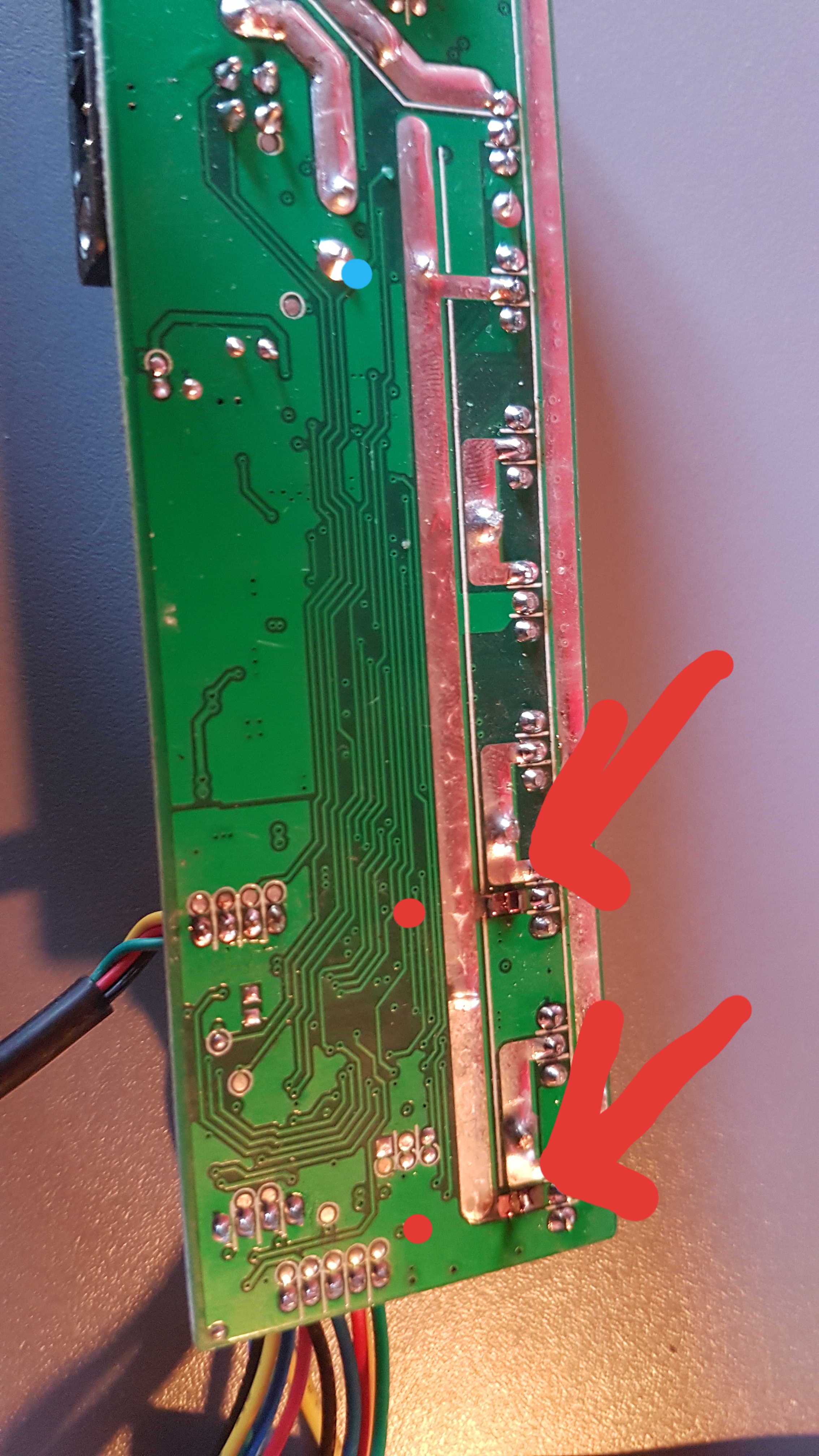
Diagram showing the common weak points:
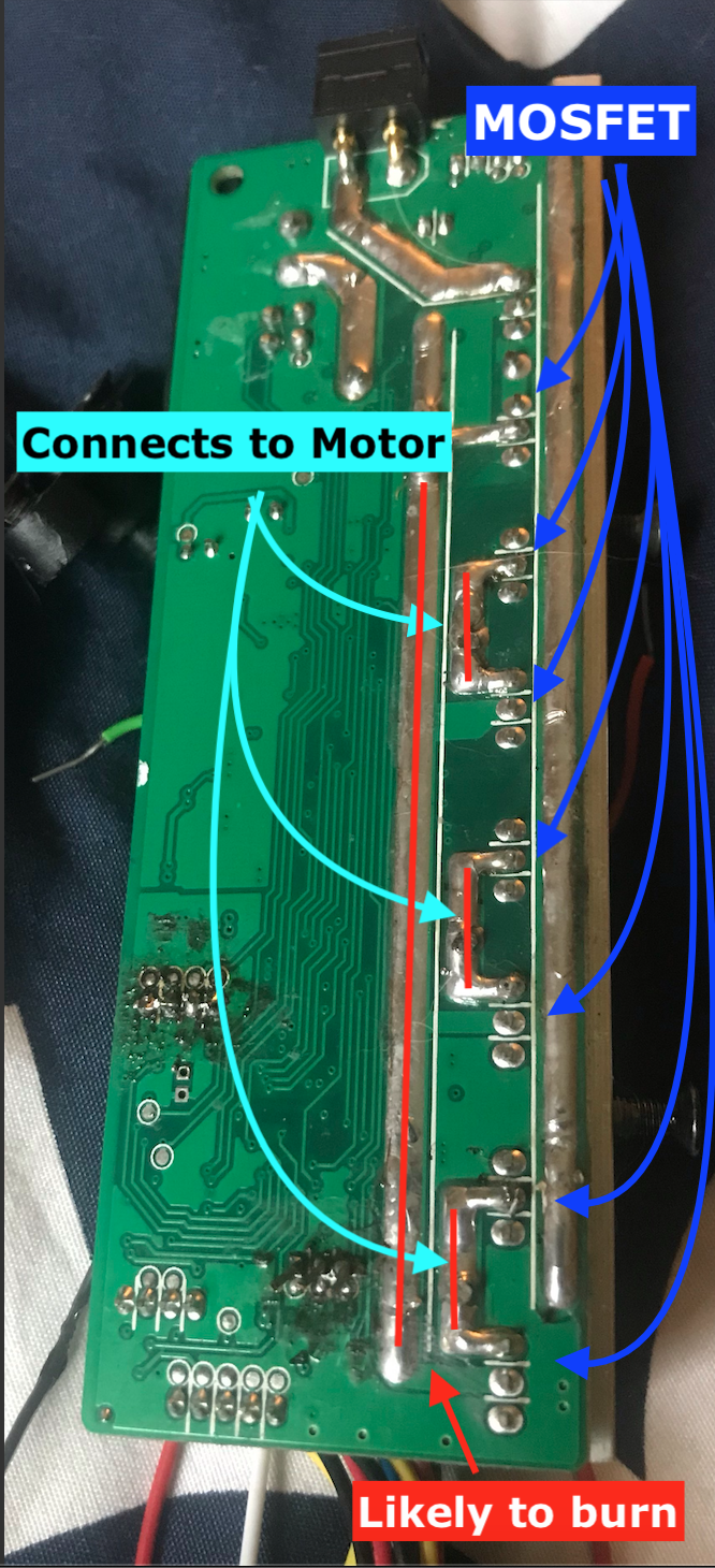
The traces marked in red are the ones which get overloaded and burn up, the Motor wires and MOSFETs are connected to the same traces, I believe the motor is throwing too much energy back into the circuit and frying it. What kind of components can I put in place to shield the circuit from the surge of energy? The normal voltage on this controller is 36 volts.
The community would greatly appreciates any help you can offer to resolve this long standing problem.
Kiki
Along with about 80% of the other riders, I've had the unfortunate experience of frying the controller on my Ninebot ES2/ES4. After researching online I came to the conclusion that these boards are flawed in their design and many consumers are having to replace their control boards after as little as 3 weeks of normal use. OEM control boards (not clones) go for about $75-$100.
What seems to be triggering the board failure is use of the electric recuperative brake. If you read the reviews and forums you'll find that people are simply told not to use it or risk frying their board.
The board has weak solder traces on the back which share a common path to the MOSFETs. So luckily the traces blow long before the MOSFETs can be damaged - this means anyone with basic soldering skills can fix their own board. I personally have beefed up my solder traces but that ended up damaging the MOSFETs during the next incident. Some out there are just buying new boards each time.
I have a good understanding of electronics and i'm also a developer, what I'd really like to do is figure out a way to modify this board so that it can cope with the surges created by using the recuperative electric brake. After researching a bit online some suggest adding capacitors to the board to absorb the load but my research shows that caps are good for mitigating high frequency short duration spikes. In the case of the recuperative e brake the voltage / amperage generated would be considered long duration.
My goal is to be able to solder some protective components to the board or possibly attach another circuit to key places on the controller to deal with the excess energy. Ideally the energy would route to something like a headlight or dissipate as heat.
I would like some advice on what components would work best for this application so I'm hoping someone here with an electronics or engineering background can point me in the right direction:
- Add capacitors?
- Add a load dump circuit which would take excess energy and route it to another place (like a light or a battery or something)
- Add a gas discharge tube - these are relatively slow devices but once activated, they can shunt a lot of energy away
- Add a Transient Voltage Suppression (TVS) diode
- Add a metal oxide varistor - A MOV protects electronic components by suppressing the voltage when it exceeds a certain threshold and safely discharging the excessive energy.
Burnt traces after using the e-brake:

Diagram showing the common weak points:

The traces marked in red are the ones which get overloaded and burn up, the Motor wires and MOSFETs are connected to the same traces, I believe the motor is throwing too much energy back into the circuit and frying it. What kind of components can I put in place to shield the circuit from the surge of energy? The normal voltage on this controller is 36 volts.
The community would greatly appreciates any help you can offer to resolve this long standing problem.
Kiki


