This is somewhat in response to the following threads:
http://endless-sphere.com/forums/viewtopic.php?f=3&t=13664&p=206093
http://endless-sphere.com/forums/viewtopic.php?f=2&t=13825&p=206434
etc.
Anyways, on the subject of the overall accuracy of the motor simulator, it's been fairly easy to confirm the simulation with actual test data in the mid to the upper end of the speed range. With direct drive hub motors, the results in the designed power levels are about as good as we could expect.
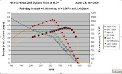
For instance, I put the 2805 winding Nine Continent motor up on the simulator database over a month ago without having actually tested it, just by extrapolating the parameters that we'd expect based on the known parameters of the 2806 hub (so 6/5 the RPM/V, (5/6)^2 the winding resistance and winding inductance, and 6/5th the no load current). Just last week I got around to doing an actual dynamo test to see how the real data stacked up against the simulator. I used a nominally 35A controller that had an actual current limit more like 38A. This is the result based on the motor parameters originally selected:
Not bad for sure, but it could certainly use a bit of tweaking. Before I began the dynamo test, I measured the actual motor phase resistance by putting exactly 10.0 amps through one of the windings and looking at the voltage drop. 0.96 volts meant just 0.096 ohms of winding resistance. Plugged that value into the simulator, adjusted the kV ever so slightly, and got this:
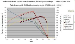
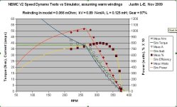
Notice how at the high end of the speed range the measured data plots against the simulator results almost perfectly, you couldn't really ask for a better fit. However, as the motor gets more and more loaded, the data starts to deviate, and below about 300 rpm you can really see that the measured torque, power, and efficiency are all lower than what the simulation curves predict.
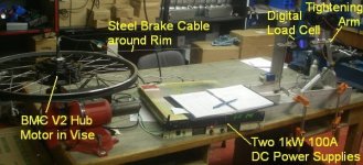
The whole process to measure the torque and current on the dynamo, slow the load motor down by 10rpm, repeat the measurements, etc. takes about 15-20 minutes. By the END of the dynamo testing (note that the data is collected right to left, I finished with the 200rpm values), the motor windings had heated up somewhat, it now measured at 0.128 ohms.
So, plug the end-of-test motor winding resistance into the simulator parameters, and now the graphs look like so:
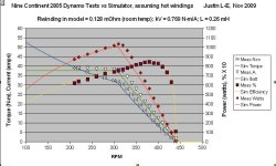
ie. now the data matches perfectly at the loaded end where the windings had heated up, but at the higher end of the speed range when the windings were still relatively cool, there is a fair bit of deviation, with the actual data looking better than the model, as expected. If, instead of choosing a fixed value for Rwinding, I was to use the actual time-dependent resistance in the model, then the data would line up perfectly over the whole graph.
When I picked the value of the winding resistance to use in the online simulator, I would usually measure the value at room temperature and increase this by about 20% to have a 'typical' resistance of what the winding might be in practice. But the reality is that the motor insides can range anywhere from sub zero to 150+ degrees celcius in the course of normal usage, so no single value will be representative.
It would be possible to have a slider bar on the simulator where you can adjust the winding temperature and see how this affects the power output, with some guidelines on how hot you could expect the motor to reach in different situations.
http://endless-sphere.com/forums/viewtopic.php?f=3&t=13664&p=206093
http://endless-sphere.com/forums/viewtopic.php?f=2&t=13825&p=206434
etc.
Anyways, on the subject of the overall accuracy of the motor simulator, it's been fairly easy to confirm the simulation with actual test data in the mid to the upper end of the speed range. With direct drive hub motors, the results in the designed power levels are about as good as we could expect.
For instance, I put the 2805 winding Nine Continent motor up on the simulator database over a month ago without having actually tested it, just by extrapolating the parameters that we'd expect based on the known parameters of the 2806 hub (so 6/5 the RPM/V, (5/6)^2 the winding resistance and winding inductance, and 6/5th the no load current). Just last week I got around to doing an actual dynamo test to see how the real data stacked up against the simulator. I used a nominally 35A controller that had an actual current limit more like 38A. This is the result based on the motor parameters originally selected:

Not bad for sure, but it could certainly use a bit of tweaking. Before I began the dynamo test, I measured the actual motor phase resistance by putting exactly 10.0 amps through one of the windings and looking at the voltage drop. 0.96 volts meant just 0.096 ohms of winding resistance. Plugged that value into the simulator, adjusted the kV ever so slightly, and got this:

Notice how at the high end of the speed range the measured data plots against the simulator results almost perfectly, you couldn't really ask for a better fit. However, as the motor gets more and more loaded, the data starts to deviate, and below about 300 rpm you can really see that the measured torque, power, and efficiency are all lower than what the simulation curves predict.
The whole process to measure the torque and current on the dynamo, slow the load motor down by 10rpm, repeat the measurements, etc. takes about 15-20 minutes. By the END of the dynamo testing (note that the data is collected right to left, I finished with the 200rpm values), the motor windings had heated up somewhat, it now measured at 0.128 ohms.
So, plug the end-of-test motor winding resistance into the simulator parameters, and now the graphs look like so:

ie. now the data matches perfectly at the loaded end where the windings had heated up, but at the higher end of the speed range when the windings were still relatively cool, there is a fair bit of deviation, with the actual data looking better than the model, as expected. If, instead of choosing a fixed value for Rwinding, I was to use the actual time-dependent resistance in the model, then the data would line up perfectly over the whole graph.
When I picked the value of the winding resistance to use in the online simulator, I would usually measure the value at room temperature and increase this by about 20% to have a 'typical' resistance of what the winding might be in practice. But the reality is that the motor insides can range anywhere from sub zero to 150+ degrees celcius in the course of normal usage, so no single value will be representative.
It would be possible to have a slider bar on the simulator where you can adjust the winding temperature and see how this affects the power output, with some guidelines on how hot you could expect the motor to reach in different situations.


