Would like to propose a discussion on the merits of integrating a Supercapacitor bank with Lithium-Ion batteries in EV's
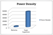
Supercapacitors are suited for the one dedicated function as a very efficient “Kinetic Energy Recovery System (KERS)”. Supercapacitors are a complimentary device to the Lithium-Ion Batteries to improve the overall system efficiency in an Electric Vehicle powertrain. Most of the gains are obtained from the very low ESR of Supercapacitors for their weight and volume, along with their much higher power density per kg and only used over short time periods.
Below is an actual graphed Tesla Model S P100D during an acceleration run from 0-60 in 2.7 seconds including roll out.
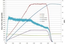
The important detail to pick up in the above graph is the rather large 77 Volt drop in the green line. The combined power extracted from the Battery is 716,000 Joules of peak power per second including its internal loss (lost as heat) of 141,000 Joules which combines with 575 kW delivered as electrical energy at the terminal. The nominal P100D Battery ESR is around 42 mΩ’s in launch mode which is estimated from that observed 77 Volt voltage drop. The energy transfer efficiency of the battery in this situation is 80% of the total energy released at peak power. So that 20% of energy lost released as heat internally in the battery and is in addition to all other losses in the powertrain, gear box, rolling resistance etc. When we take the total energy in to what ends up stored kinetically in the mass of the vehicle it comes out to 61%.
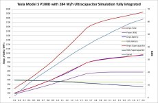
The following is a simulation graph of how much more efficient a Model S P100D becomes when an only 284 W/h Supercapacitor weighing about 55 kg is integrated into the powertrain.
My simulation dataset only goes out to 2.8 seconds. Would like to gain a larger dataset as my simulation software will be able to provide some interesting numbers from say an hour’s worth of real world driving.
There is a calculated 60% reduction to the 141,000 Joules energy lost as heat in the battery when the Supercapacitor is in a 50/50 power sharing mode for those 2.8 seconds during acceleration.
The Supercapacitor bank has a very low ESR for its volume and weight at only ~27-28 mΩ’s. When integrated into the powertrain, it reduces the battery Volt drop to around 40 volts peak instead of Battery only 77 Volts. That is a reduction of just over half and the battery peak current only reaches a peak of 950 Amps, along with the Supercapacitor delivering the balance. Considering the battery doesn’t need to be pre heated to 50 Deg C for launch mode the system losses are more than halved and the battery ESR can remain at its nominal 50-52 mΩ’s. When a Supercapacitor is added in, the combined peak power losses converted into heat during acceleration is reduced to around an average of 54,000 Joules over a second at peak power hence the 60% reduction in lost energy. Looking at it another way only 80% of the total energy extracted is available at peak power from the battery only system. This improves to 91% of the total energy delivered to the drivetrain when the Supercapacitor is integrated in with the battery, that 11% is a massive improvement and cannot be ignored.
The main point here is the Supercapacitor is only a kinetic energy device with its sole function being to provide a large amount of peak power to get you up to speed over a short period (a few seconds in this case). Once the vehicle is traveling at a constant speed the Supercapacitor goes offline, but is then on standby for any breaking application to recover the maximum amount of kinetic energy having been stored in the mass of the vehicle. The amount of peak regen power from a Dual motor system could be up to 200 kW’s 3-4 times what it currently is currently available in Tesla vehicles. The cycle life of a Supercapacitor can be measure at greater than 1,000,000 cycles! Please also note the Supercapacitor is not sized to extract any “Gravitational Potential Energy” when going down a hill. This just so happens to be a much smaller amount of power when measured at per-second rate and can be still be sent back to the Battery.
The depth of discharge of the Supercapacitor at the 2.8 second mark is around 53 % which just so happens to be about the right point for capturing most the Regenerative braking energy in this simulation.
Below is a graph of the peak power of regen increased to 200 kW’s (from Dual Motors) which is less than half of the Supercapacitors peak power rating.
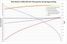
Note this is based on a form of ideal conditions simulation with the kW’s and Amps as negative numbers (-) being from the combined Dual motor inverters feed into the Supercapacitor.
The graph timeline shows the vehicle coming to a stop in around 6 seconds without the needing to use friction braking.
Many others have tried just placing a Supercapacitor bank in parallel the battery terminals without yielding much in the way system performance. This is mostly due the Supercapacitor needing to be at least 500 W/h or more to make much of a difference. That becomes a very expensive exercise when increasing the energy density of the Supercapacitor to gain any more system performance.
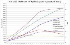
As can be seen above the 65 Volt drop across the Battery is an improvement over 77 Volts, but that is no match for my system in the second graph at 40 Volts with a 37 Volt reduction. If this parallel simulation is run for about another 1.5 seconds the Supercapacitor will begin to equalise with the battery voltage and we are back to our 77 Volt drop again with lots of heat build up to manage if the high current drain is maintained. The depth of discharge of the Supercapacitor in this example is only 26%, hence why it needs to be at least twice the capacity of my system to add any minimal benefit.
The flip side of this is when the vehicle is at a constant speed consuming say around 17-18 kW’s (~290W per mile) at 60 MPH, the battery will begin back feed a lot of current back into the Supercapacitor. This high current will start off at around 650A and then progressively roll back from there, as the Supercapacitor SOC increases to equalisation with the Battery at some point over the next few seconds. Once the Supercapacitor is at this equalisation SOC and the Regen braking is applied, it is of little assistance with the change in SOC difference being so small the battery will end up soaking most of the regen energy within just over a second. Back to our limit of 50-60 kW’s of regen.
This is not the case with my proposed system, as the vast majority of the recovered Regen braking energy can be prioritised to the Supercapacitor which can also be about half size of the above parallel example, a significant cost saving.
Below is another system architecture example of how many others have tried to integrate a Supercapacitors via DC-DC converter to power inverter with the battery in parallel again.
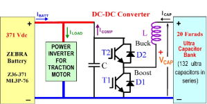
This still has fundamental problems using an expensive Buck/Boost (DC-DC) converter adding additional complexity along with being somewhat current limited. Buck/Boost (DC-DC) converters due to size and weight constraints are peak power limited to 60-100 kW’s.
Instead my approach is to use separate inputs into the Drivetrain power inverter without the need to use a “current limiting DC-DC converter”. The Supercapacitor can transfer >400 kW of peak power for just over second when it’s needed, so isn’t the “limiting factor”.
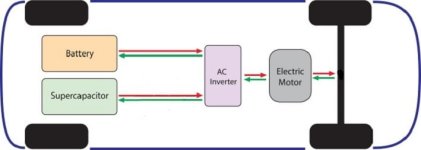
The complexity of my system is in Drivetrain inverter(s). It’s cheaper to just added more silicon switching devices rather than having a very large expensive inductor in DC-DC converter which just so happens to pre-exist in the traction motor winding's. After all that’s what the Regenerative braking mode makes use of, those 3 coils in the motor.
The following is list of benefits a small Supercapacitor bank has the potential to provide;
1. Greater peak power at acceleration with the potential to supply enough to a Tri motor Drive train setup (800+ kW’s) not currently possible with the most Tesla battery packs power density. Example the current Tesla Model S P100D battery pack is output limited to 580 kW’s of power in launch mode and with the battery pre heated to 50 Deg C. When not in Launch mode the power density reduces to around 460 kW peak. The Supercapacitor (550 W/h’s) can deliver an additional 400 kW’s for a few seconds, with no requirement to pre heat the battery to its 20% lower ESR another to increase the battery only peak current yield without the battery voltage sagging too low. Yes the new Plaid Model S is rated at 800+ kW’s, but can it do 200 kW’s of regen braking when the Battery is at a SOC of >80%? No it will never be able too.
2. System efficiency can be improved by around 10-15%, translating to a range boost and/or improved top end performance. This 10-15% is a return loss number that depending on the configuration could end up being higher and go up to 20% depending on how well it integrates into the system. This range improvement is mostly yielded in City/Urban driving with that dropping to less than half for highway driving. Please note the range boost is not directly correlated with efficiency gain but will still be a meaningful number.
3. An increase in battery life. This being achieved by removing the high peak current demands both during acceleration and regen braking, thus reducing the battery internal temperature rise. Also prioritising the regenerative braking energy to the Supercapacitor reduces the number of part charge cycles a Battery only system would receive (Gravitational Potential energy is still sent to the Battery).
4. Energy used for thermal management of the Battery temperature can be reduced, translating into an additional reduction in total energy consumption. That energy to drive the cooling process has to come from somewhere. This may not be much over short period, but will add up during longer trips involving continuous driving.
5. The Battery can become slightly smaller, with the space and weight freed up, available for the Supercapacitor bank along with a Capacitor Management System.
6. A cheaper type of battery could be used by making the anode and cathode materials thinner which should translate into a bill of materials saving. This proposal is only for cost sensitive applications. The main aim would to be go for higher energy density and not be so concerned by an increase the resulting internal resistance (ESR) and would need to be very carefully weighed up if the benefit is there. This higher Battery ESP would be offset by the Supercapacitor at times of high peak power demand. The battery is the single most expensive component in the electric vehicle, currently representing around 40-50% of the total materials cost (this cost is dropping though).
7. A much higher level of Regenerative Energy can be recovered from a Dual motor configuration as the Supercapacitor has very high specific power density that is not possible with a battery only system. Currently Regenerative Braking Energy is limited to around a maximum of only 50-60 kW, which could be increased upwards to 150-200 kW’s with a Dual Motor configuration.
Currently battery only systems @ 80-100 % State of Charge, it’s not as much Regenerative Braking energy can be recovered due to exceeding the Batteries highest terminal voltage with high bursts of power over short periods of time. The Supercapacitor solves this problem by being at a much lower State of Charge due to it providing most of the energy to accelerate the vehicle initially.
Supercapacitors are suited for the one dedicated function as a very efficient “Kinetic Energy Recovery System (KERS)”. Supercapacitors are a complimentary device to the Lithium-Ion Batteries to improve the overall system efficiency in an Electric Vehicle powertrain. Most of the gains are obtained from the very low ESR of Supercapacitors for their weight and volume, along with their much higher power density per kg and only used over short time periods.
Below is an actual graphed Tesla Model S P100D during an acceleration run from 0-60 in 2.7 seconds including roll out.

The important detail to pick up in the above graph is the rather large 77 Volt drop in the green line. The combined power extracted from the Battery is 716,000 Joules of peak power per second including its internal loss (lost as heat) of 141,000 Joules which combines with 575 kW delivered as electrical energy at the terminal. The nominal P100D Battery ESR is around 42 mΩ’s in launch mode which is estimated from that observed 77 Volt voltage drop. The energy transfer efficiency of the battery in this situation is 80% of the total energy released at peak power. So that 20% of energy lost released as heat internally in the battery and is in addition to all other losses in the powertrain, gear box, rolling resistance etc. When we take the total energy in to what ends up stored kinetically in the mass of the vehicle it comes out to 61%.
The following is a simulation graph of how much more efficient a Model S P100D becomes when an only 284 W/h Supercapacitor weighing about 55 kg is integrated into the powertrain.

My simulation dataset only goes out to 2.8 seconds. Would like to gain a larger dataset as my simulation software will be able to provide some interesting numbers from say an hour’s worth of real world driving.
There is a calculated 60% reduction to the 141,000 Joules energy lost as heat in the battery when the Supercapacitor is in a 50/50 power sharing mode for those 2.8 seconds during acceleration.
The Supercapacitor bank has a very low ESR for its volume and weight at only ~27-28 mΩ’s. When integrated into the powertrain, it reduces the battery Volt drop to around 40 volts peak instead of Battery only 77 Volts. That is a reduction of just over half and the battery peak current only reaches a peak of 950 Amps, along with the Supercapacitor delivering the balance. Considering the battery doesn’t need to be pre heated to 50 Deg C for launch mode the system losses are more than halved and the battery ESR can remain at its nominal 50-52 mΩ’s. When a Supercapacitor is added in, the combined peak power losses converted into heat during acceleration is reduced to around an average of 54,000 Joules over a second at peak power hence the 60% reduction in lost energy. Looking at it another way only 80% of the total energy extracted is available at peak power from the battery only system. This improves to 91% of the total energy delivered to the drivetrain when the Supercapacitor is integrated in with the battery, that 11% is a massive improvement and cannot be ignored.
The main point here is the Supercapacitor is only a kinetic energy device with its sole function being to provide a large amount of peak power to get you up to speed over a short period (a few seconds in this case). Once the vehicle is traveling at a constant speed the Supercapacitor goes offline, but is then on standby for any breaking application to recover the maximum amount of kinetic energy having been stored in the mass of the vehicle. The amount of peak regen power from a Dual motor system could be up to 200 kW’s 3-4 times what it currently is currently available in Tesla vehicles. The cycle life of a Supercapacitor can be measure at greater than 1,000,000 cycles! Please also note the Supercapacitor is not sized to extract any “Gravitational Potential Energy” when going down a hill. This just so happens to be a much smaller amount of power when measured at per-second rate and can be still be sent back to the Battery.
The depth of discharge of the Supercapacitor at the 2.8 second mark is around 53 % which just so happens to be about the right point for capturing most the Regenerative braking energy in this simulation.
Below is a graph of the peak power of regen increased to 200 kW’s (from Dual Motors) which is less than half of the Supercapacitors peak power rating.

Note this is based on a form of ideal conditions simulation with the kW’s and Amps as negative numbers (-) being from the combined Dual motor inverters feed into the Supercapacitor.
The graph timeline shows the vehicle coming to a stop in around 6 seconds without the needing to use friction braking.
Many others have tried just placing a Supercapacitor bank in parallel the battery terminals without yielding much in the way system performance. This is mostly due the Supercapacitor needing to be at least 500 W/h or more to make much of a difference. That becomes a very expensive exercise when increasing the energy density of the Supercapacitor to gain any more system performance.

As can be seen above the 65 Volt drop across the Battery is an improvement over 77 Volts, but that is no match for my system in the second graph at 40 Volts with a 37 Volt reduction. If this parallel simulation is run for about another 1.5 seconds the Supercapacitor will begin to equalise with the battery voltage and we are back to our 77 Volt drop again with lots of heat build up to manage if the high current drain is maintained. The depth of discharge of the Supercapacitor in this example is only 26%, hence why it needs to be at least twice the capacity of my system to add any minimal benefit.
The flip side of this is when the vehicle is at a constant speed consuming say around 17-18 kW’s (~290W per mile) at 60 MPH, the battery will begin back feed a lot of current back into the Supercapacitor. This high current will start off at around 650A and then progressively roll back from there, as the Supercapacitor SOC increases to equalisation with the Battery at some point over the next few seconds. Once the Supercapacitor is at this equalisation SOC and the Regen braking is applied, it is of little assistance with the change in SOC difference being so small the battery will end up soaking most of the regen energy within just over a second. Back to our limit of 50-60 kW’s of regen.
This is not the case with my proposed system, as the vast majority of the recovered Regen braking energy can be prioritised to the Supercapacitor which can also be about half size of the above parallel example, a significant cost saving.
Below is another system architecture example of how many others have tried to integrate a Supercapacitors via DC-DC converter to power inverter with the battery in parallel again.

This still has fundamental problems using an expensive Buck/Boost (DC-DC) converter adding additional complexity along with being somewhat current limited. Buck/Boost (DC-DC) converters due to size and weight constraints are peak power limited to 60-100 kW’s.
Instead my approach is to use separate inputs into the Drivetrain power inverter without the need to use a “current limiting DC-DC converter”. The Supercapacitor can transfer >400 kW of peak power for just over second when it’s needed, so isn’t the “limiting factor”.

The complexity of my system is in Drivetrain inverter(s). It’s cheaper to just added more silicon switching devices rather than having a very large expensive inductor in DC-DC converter which just so happens to pre-exist in the traction motor winding's. After all that’s what the Regenerative braking mode makes use of, those 3 coils in the motor.
The following is list of benefits a small Supercapacitor bank has the potential to provide;
1. Greater peak power at acceleration with the potential to supply enough to a Tri motor Drive train setup (800+ kW’s) not currently possible with the most Tesla battery packs power density. Example the current Tesla Model S P100D battery pack is output limited to 580 kW’s of power in launch mode and with the battery pre heated to 50 Deg C. When not in Launch mode the power density reduces to around 460 kW peak. The Supercapacitor (550 W/h’s) can deliver an additional 400 kW’s for a few seconds, with no requirement to pre heat the battery to its 20% lower ESR another to increase the battery only peak current yield without the battery voltage sagging too low. Yes the new Plaid Model S is rated at 800+ kW’s, but can it do 200 kW’s of regen braking when the Battery is at a SOC of >80%? No it will never be able too.
2. System efficiency can be improved by around 10-15%, translating to a range boost and/or improved top end performance. This 10-15% is a return loss number that depending on the configuration could end up being higher and go up to 20% depending on how well it integrates into the system. This range improvement is mostly yielded in City/Urban driving with that dropping to less than half for highway driving. Please note the range boost is not directly correlated with efficiency gain but will still be a meaningful number.
3. An increase in battery life. This being achieved by removing the high peak current demands both during acceleration and regen braking, thus reducing the battery internal temperature rise. Also prioritising the regenerative braking energy to the Supercapacitor reduces the number of part charge cycles a Battery only system would receive (Gravitational Potential energy is still sent to the Battery).
4. Energy used for thermal management of the Battery temperature can be reduced, translating into an additional reduction in total energy consumption. That energy to drive the cooling process has to come from somewhere. This may not be much over short period, but will add up during longer trips involving continuous driving.
5. The Battery can become slightly smaller, with the space and weight freed up, available for the Supercapacitor bank along with a Capacitor Management System.
6. A cheaper type of battery could be used by making the anode and cathode materials thinner which should translate into a bill of materials saving. This proposal is only for cost sensitive applications. The main aim would to be go for higher energy density and not be so concerned by an increase the resulting internal resistance (ESR) and would need to be very carefully weighed up if the benefit is there. This higher Battery ESP would be offset by the Supercapacitor at times of high peak power demand. The battery is the single most expensive component in the electric vehicle, currently representing around 40-50% of the total materials cost (this cost is dropping though).
7. A much higher level of Regenerative Energy can be recovered from a Dual motor configuration as the Supercapacitor has very high specific power density that is not possible with a battery only system. Currently Regenerative Braking Energy is limited to around a maximum of only 50-60 kW, which could be increased upwards to 150-200 kW’s with a Dual Motor configuration.
Currently battery only systems @ 80-100 % State of Charge, it’s not as much Regenerative Braking energy can be recovered due to exceeding the Batteries highest terminal voltage with high bursts of power over short periods of time. The Supercapacitor solves this problem by being at a much lower State of Charge due to it providing most of the energy to accelerate the vehicle initially.


