Bayliner Conversion

no they dont want you pulling them onboard
i just layed down on the swim grid and held it by the mouth for a couple minutes til it kicked
they have no teeth, gold eyes and between the upper lip and nose and whiskers it had what looked like about 80 little paw prints like a dog was running all over his nose
i could probably modify the kite boarding belt quite easily into a fighting belt and that should raise the reel into view

every time i post i get, Thread Starter, in green banner/white letters. is that normal?
 
anyone use Xometry for 3d metal parts

problem im having is i put in the stl file from Cura and i get quoted for a nylon coupling instead of an aluminum one

i guess i need to find a way to convert my free cad drawings another way

they say there is a 1-2% shrinkage on the metal just like the plastic filaments

theres 3 different processes

a few different metals to choose from but i think the aluminum will be fine
 
i figured it out, just click on nylon and choose different material
for metal binder jetting the coupling is $140 to $200 for 316ss, 316ss/bronze or 420i ss/bronze but it has a rough texture/finish
for DMLS aluminum its $450 and it has a rough texture/finish also, the stainless is $800

i think im just going to order the 420 ss/bronze for $140 with the same file i used for the nylon/cf coupling because im usually 0.2 or 0.3 oversize on the holes to allow for shrinkage

for $140 it ships within 10 business days/2 weeks
economy $110 ships within 15 business days/3 weeks

they have some kind of referal award program where i get a $50 credit on future purchases over $100 and the person i refer gets a $50 credit on their order over $100. i can try putting the link here if thats allowed so another member can save $50
 
converted morse controls to a potentiometer with a 50mm diameter gear on the lever and a 80mm gear on the potentiometer


hardware guy teaches you had to make gears in freecad

 
got my 3d printed metal shaft coupling today and im pretty impressed
i sent them my file that i used for the ender and it specked right out the same as the plastic ones so the shrinkage seems to be at the same rate as the plastic filaments

 
Last edited:
got my 3d printed metal shaft coupling today and im pretty impressed
i sent them my file that i used for the ender and it specked right out the same as the plastic ones so the shrinkage seems to be at the same rate as the plastic filaments

i was impressed until i put it on
the z-axis is off by about 3/32 so it is unusable
im going to call it The Leaning Tower of Xometry coupling
they need to calibrate their printer
 
That's almost hard to believe that a 3d printing company does not know how to calibrate a printer? But I can see it with my own eyes. That part with the whole motor shaking like hell should be enough to get them to at least replace or refund. Hope the insults doesn't piss them off to much. :mrgreen: Even though they sure deserve it.
 
That's almost hard to believe that a 3d printing company does not know how to calibrate a printer? But I can see it with my own eyes. That part with the whole motor shaking like hell should be enough to get them to at least replace or refund. Hope the insults doesn't piss them off to much. :mrgreen: Even though they sure deserve it.
theyre sending me a new one:) fingers crossed

im just going to put this here,new tech hybrid engine

 
Last edited:
got an email from Xometry today
here it is

"Binder jetting is tricky because we can only guarantee 1% tolerance on the bounding box of the part, how the internal geometry shrinks or grows is not accounted for. We provided within 1% of the bounding box, but in the world of engines, 1% is a huge tolerance. We could reprint this part 100 times and still see a wobble. If you wanted a reprint to fix the height issue, we could do that, but we don't believe that would give you a complete solution.

For printing, DMLS would be a better choice as the tolerance are linear instead of a percent. The same part would cost about $895.21 in this technology. I imagine that is why you chose Binder Jetting. "

heres my reply to them

"hi Vicki, if this technology cant produce a vertical piece as in 90 degrees straight up then why would anyone even use it or even buy one?
it sounds like you are saying it cant print a square cube
this is not a difficult piece to do
why did i choose metal binder jetting? because i read this on your website

Use Metal Binder Jetting for Fast and Affordable Metal Parts​

Metal binder jetting technology is a 3D printing technology used to make complex metal parts with excellent mechanical properties. Our partnership with ExOne provides on-demand production capacity with the latest binder jet machines and high-performance metal alloys and composites.
Metal binder jetting is often used to produce metal binder parts at fraction of the cost of other metal processes with virtually no design limitations. Binder jetting machines have large build areas and produce parts at high speed, making it an excellent option for low to medium batch, rapid turn parts. The speed and affordability of binder jetting make it perfect for industries that need high strength parts such as industrial, automotive, consumer products, oil, and gas industries.


i used to be #1 in sales and #1 in customer satisfaction, it was a hard thing to do, most guys will be good at sales and suck at customer service or vice versa
if i screwed up, i would own it. my boss would try to blame it on something else and make into an up sale but its all about perception
i would inform the customer, give 2 or 3 options and let them decide

no one in automotive,industrial, oil and gas would use this technology that has no design limitations (meaning complex)if it cant print straight up. my part is not complex its basic
the z-axis was off, it printed straight up but on an angle, it wasnt curved or warped.

it sounds to me like your boss is trying to turn this into an upsale

for me, its been a week and im thinking of sending this file to another company to see if its the technology or if im being fed an excuse to open my wallet

its up to you guys whether you send me a part that was printed on a properly calibrated machine or not but im not sending any more money your way, i chopped the coupling in half and now i have 2 expensive paper weights sitting on my desk. like i said, its already been a week and you still havent even made the part yet, i have a couple more designs i need done but this really isnt a good first impression.
i still cant even log into your site"

wait and see what happens i guess

did some googling to see what printers they use

ExOne metal binder jetting


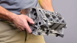
they print cylinder blocks
1689739499409.png
 
Last edited:
im done talking with them, see if they send me one
i made the video public tonight

did some prop testing with another nylon carbon fiber coupling today that had what i consider bad layer adhesion
it did very well, hit 130 celsius at 40 amps continuous before i had to shut down after 45 minutes because of low battery and there was a noise at the end, thought the coupling melted but the insert slipped.
i kept the test going at 26 amps and the motor temps were down to 118 C after 1 hour
going to do another test tomorrow with a charged battery and the insert was sika flexxed

you can see the coupling at the end of the video, unscathed


the nylon/cf is supposed to be good to 167 celsius so im just going to let the motor run and hopefully the motor temps level off before i hit 150 celsius

 
did a speed test with the 3 blade 9.25/12 3 blade prop at roughly 3kw continuous, its only 3.3 knots
then ran the motor for 1hr25 minutes at 3 kw
the motor reached 146C and the coupling held
swapped out props to the 4 blade and will do more testing tomorrow
but Denzel has a DA95S motor
supposed to be 5kw/150C at 3300rpm and should be just a plug and play swap, the motor shaft is 3mm longer but i think i have room for it.
but basically im going to run the motor at 5kw, check motor rpm and see if the coupling blows at 5kw/150C with the 4 blade

 
From their video..
..” you have to allow 19-20%. Shrinkage”
..which to me says they can never be precision components, and anything that needs to be a good fit would have to be machined after printing and sintering.
At best you have a metal sintered component ( ie, not a high strength compared to billet)
for a simple part like your coupler, it would be a breeze for a machine shop to turn one out in an hour from a solid bar stock.
their website says 1% to 2% shrinkage

when you print with plastics you have to allow for shrinkage

i gambled and sent the file i used for the carbon fiber coupling and the metal one spec'd out perfect. the z-axis was off because it wasnt calibrated. got an email today saying theyre sending one from a properly calibrated printer and a $110 off my next purchase. im going to try and get some 6mm carbon fiber cut and drilled for new suspension linkage i designed for a Begode Master euc and see how that turns out or maybe i should see if they have some high temp/strength plastics that out perform the nylon carbon fiber from filaments.ca

people buy these printers and put them in their garage/barn/house then Xometry will send them a print job to do.
i dont know where that coupling was printed but im pretty sure the new one will be printed by someone that knows what theyre doing
 
As i said,…
from their video @ 1:25 …….the digital file……” you have to allow 19-21% for shrinkage”…??

ya but that guy looked like hippie, he was probably stoned while making the video
 
tried running the coupling at 160C but at 155C/5000 watts the motor started to run cooler, the temps started dropping quickly
i remember Alex from Denzel saying something about the temperatures

i think theres something screwy going on with the sensor so i set the overheat s/d at 155C


xometry can only cut 0.125 cf

emailed alex at denzel to see if i can get some torque curves for the motors

at 5kw the da85-6 motor spins at 2470 rpm (80amps) and produces 54nm torque on the shaft (amps arent given)

the da95s at 5kw spins at 3300 rpm and produces 83nm at 275 amps

with just that information with no torque curve sheets
id gain 830 rpm at 5kw's
that should get me to hull speed
 
Back
Top