Upload Your Circuit Schematics & Requests Here...

Hello.
I recently broke the trunk of my bike where my 48v battery was stored and decided to put the battery in the frame also I added three cells to battery and changed the BMS to 16S.
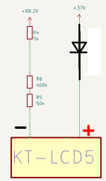
After reading this post about problems with high voltage. I decided to lower the LCD voltage. After reading this post about problems with high voltage. I decided to lower the LCD voltage. The simplest option that I see is to add two more leads to the battery instead of dc-dc converter fom here
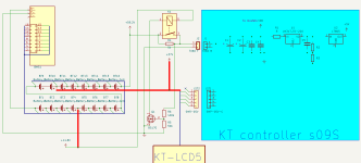
What do you think if this schematic ?
1.png
The first pin of the display must be disconnected from the connector and connected to + 37V
mosfet Q1 allow close the relay contacts when the voltage on the controller capacitors reaches approximately 40V (R6/R5 - can adjust the required voltage to open the relay)
 
Pulling voltages from taps on the battery has a few problems. One, is the current draw will be uneven between cell groups and cause the battery to get out of balance. This imbalance will be more than the BMS is able to correct in a reasonable amount of time. The other potential issue is if the pack BMS trips, it disconnects the B- from the load, which will swing up to B+ voltage. This might fry anything connected to the taps.

There are some linear "voltage dropper" circuits you could put between the pack and the display, or you could use a small dc-dc converter if you can find one with a common negative or an isolated one. Depending on the display current requirements, just a TVS diode in series might work. The diode will need to dissipate some heat, which depends on the display current. The diode will need a heat sink of some sort. For higher currents, a more complex circuit would be needed.
 
One, is the current draw will be uneven between cell groups and cause the battery to get out of balance. This imbalance will be more than the BMS is able to correct in a reasonable amount of time.
Thanks a lot for the comments.
as I understand it, I need to check the current of the control systems and select the BMC such that the balancing current exceeds the currents of the control systems.
The other potential issue is if the pack BMS trips, it disconnects the B- from the load, which will swing up to B+ voltage. This might fry anything connected to the taps.
Do you mean this kind of situation?

3.png
Thank you for your help.
There are some linear "voltage dropper" circuits you could put between the pack and the display, or you could use a small dc-dc converter if you can find one with a common negative or an isolated one.
My intuition tells me that spending energy on balancing is better than on a linear regulator or step-down
 
Last edited:
Not sure I understand your drawing, but if you look at your original schematic, imagine the P- connection from the BMS getting connected to B+. Things running off the taps will have reverse polarity. A diode can prevent reverse current, so would be a good idea there.

Most typical BMS units can only balance at 20-50 mA. If you know what the display current is, you can do the math on how long it would take the balancing circuit to restore the balance. This also means you have to charge the pack fully every time to get the balancing to work.

They do make active balancers that run all the time, but they are not very reliable and tend to drain the pack over time.

If the display current is less than 100mA, I think a single 12v TVS diode in series with the display power will work OK. 1.2W of dissipation isn't too bad.
 
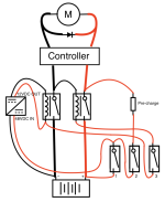
Hello! I'm a beginner and would really appreciate some feedback on the following circuit diagram and the proposed components.

The thought here is that the switches 1, 2 and 3 should be flicked (and remain closed) in order for starting/running.
1. Power 12VDC converter for relays (and ancillaries, lights etc. TBD) and closes the high-power negative.
2. Pre-charge to controller.
3. Closes high-power positive to controller.
thoughts.png
Fuses are omitted, but planned, I still need to figure out appropriate values. Please find all information below:

Repetitive peak reverse voltage (VRRM) - Motor input voltage: 48VDC
Average forward current (IFAV) - Motor rated current: 34A
Surge forward current (IFSM) - Motor maximum current: 42A

Full state, initial discharge voltage (VBat,full,initial,D): 54.6VDC
Maximum continuous battery discharge current (IBat,cont,D,max): 40A

DC/DC converter: RSD-30L-12
spec: https://www.meanwell-web.com/content/files/pdfs/productPdfs/MW/RSD-30/RSD-30-spec.pdf
(V,in): 18 - 72VDC
(V,out): 12VDC
Rated current: 2.5A

Relay/Contactor:
DCNLM50NB12
spec: https://www.littelfuse.com/media?re...filename=littelfuse-contactor-dcnlm-datasheet
Coil voltage rating: 12VDC
Switching voltage rating (nominal/maximum): 48VDC/60VDC
Current rating continuous: 50A

or

TC-GSR-1-100DD (requires heatsink)
spec: https://asset.conrad.com/media10/ad...ung-max-220-vdc-gleichstromschaltung-1-st.pdf
Coil voltage rating: 3 - 32VDC
Switching voltage rating (nominal/maximum): 220VDC/220VDC
Current rating continuous: 100A

Pre-charge resistor: RH005
spec: https://www.vishay.com/docs/30201/rhnh.pdf
Resistance: 150 Ohms
Nominal load: 5W

Flyback/Snubber diode: DSEI60-06A
spec: https://ixapps.ixys.com/Datasheet/DSEI60-06A.pdf
VRRM: 600V
IFAV: 60A
IFSM: 550A

I've tried to match components suitably, but have no electrical experience. Confirmation or alternative suggestions would be hugely appreciated.

Some more questions:

Is the shared negative bus for 48V (from motor) and 12V (from relay coil) OK?
Would it be possible to place a LED pre-charge indicator in the circuit, as opposed to an incandescent bulb?
Would ferrite cores/rings placed before the motor terminals be recommended?

Many many thanks in advance.

All the best,
alreadyblownbudget
 
Hello! I'm a beginner and would really appreciate some feedback on the following circuit diagram and the proposed components.

Where the red curvy thin lines cross the red thick wire, are they just crossing it or connecting to it? (convention would be that they are just crossing it visually, but best to be sure)


The thought here is that the switches 1, 2 and 3 should be flicked (and remain closed) in order for starting/running.

Do you require there be three switches for some reason? (sometimes knowing the reasoning for a proposed system setup can help create a more suitable design)

If not, the circuit could be simplified.

Do you require that both positive and negative of battery-to-controller be disconnected? (there isn't normally any electrical reason to do so).

If it's a typical brushed motor controller design, it already has diodes built into the FETs, so the external flyback diode probably isn't required, unless the controller manual calls out for one, or the expected flyback voltage and/or current during motor shutoff is very high (like a high-inductance motor, etc). Won't hurt to have it, if you're not sure.

Is the shared negative bus for 48V (from motor) and 12V (from relay coil) OK?

It's a normally-done thing, so should be fine.

Would it be possible to place a LED pre-charge indicator in the circuit, as opposed to an incandescent bulb?
Sure. You can put the LED and it's dropping resistor across (paralleled with) the precharge resistor. It will be fully lit at the start, and go out when precharge is nearly done. (at whatever voltage the LED can operate at, so a common low-power red LED will have the lowest drop of about 1.2v.)


Would ferrite cores/rings placed before the motor terminals be recommended?
Shouldn't need any; the motor itself will tend to dampen the current changes. If there's a big RF problem interfering with something else, then the right size cores might help, but making the motor wire a twisted pair setup (with external shielding if necessary) should help currents cancel out.
 
Hi amberwolf! Thank you kindly for taking the time to provide me feedback :)
Where the red curvy thin lines cross the red thick wire, are they just crossing it or connecting to it? (convention would be that they are just crossing it visually, but best to be sure)
Yes, good idea to make sure, much appreciated, but yes just visually crossing. I've only connected wires at terminals in the previous diagram, either battery, relay or switch terminals. I also still need to work out fuses and distribution block positions. Maybe at the final stage.

Do you require there be three switches for some reason? (sometimes knowing the reasoning for a proposed system setup can help create a more suitable design)

If not, the circuit could be simplified.

Do you require that both positive and negative of battery-to-controller be disconnected? (there isn't normally any electrical reason to do so).
I absolutely do not require 3 switches. I was thinking to completely break that high load circuit (thicker wire/line) for, I guess extra safety or perhaps battery health, but thanks for pointing that out. If there's no benefit then I can save some money on an extra switch and relay. Awesome, many thanks! (y)

If it's a typical brushed motor controller design, it already has diodes built into the FETs, so the external flyback diode probably isn't required, unless the controller manual calls out for one, or the expected flyback voltage and/or current during motor shutoff is very high (like a high-inductance motor, etc). Won't hurt to have it, if you're not sure.
I forgot to initially mention that the motor is brushless and from the Vevor brand (Model: MY1020D 48VDC 2000W). Controller is also from Vevor (Model: BY15WF02-A). Given the low cost of these and the quality that can be assumed from that. I would lean towards having the external flyback diode as reduncancy.

Also addressing the ferrite cores and RF interference. I honestly don't know, but was thinking that the Vevor controller might be the worst RF or "noise" offender and if there was something I could do the prolong the life of the motor or other connected components then why not.

I'm unsure though on both topics and would refer to all expertise on offer.

I'm going to rework the schematic over the next days, find suitable switches and fuses. I'm finding resistor calculation a bit difficult, especially since batteries have voltage ranges, 39V - 54.6V in this case. I need to learn a bit more first. Then there's the ferrite cores, I have not found a suitable starting point for that calculation yet.

I will be back with more questions soon. Many thanks again (y)
 
I absolutely do not require 3 switches. I was thinking to completely break that high load circuit (thicker wire/line) for, I guess extra safety or perhaps battery health, but thanks for pointing that out. If there's no benefit then I can save some money on an extra switch and relay. Awesome, many thanks! (y)
Breaking a circuit at a single point still breaks the circuit. ;)

There are conditions it would be better to break both sides, but that's usually in specific usages that have some distinct possiblity of shorting across the cut circuit to reconnect it, and/or really high voltage systems, etc.


I forgot to initially mention that the motor is brushless and from the Vevor brand (Model: MY1020D 48VDC 2000W). Controller is also from Vevor (Model: BY15WF02-A). Given the low cost of these and the quality that can be assumed from that. I would lean towards having the external flyback diode as reduncancy.

If it's brushless, there are a minimum of three thick phase wires to the motor, not two, plus usually some smaller wires for position (hall) sensors (5) and possibly speed or temperature sensors (1-2+).

If you needed to install them to fix a problem, the flyback diodes would in this case actually require six, with three of them each phase to the positive rail and each phase to the negative, with diodes setup so they don't conduct under correct polarity.


Also addressing the ferrite cores and RF interference. I honestly don't know, but was thinking that the Vevor controller might be the worst RF or "noise" offender and if there was something I could do the prolong the life of the motor or other connected components then why not.
You could put cores between battery and controller, and possibly on the hall sensor cable from motor to controller at the controller end, but probably better not to on the phase wires between motor and controller. The cores are there to dampen changes in current, but the motor works by such changes.

In most cases these things are not needed; the most common thing that needs noise removal is hall signal wires, if a motor simply doesn't run right under high load despite the correct phase/hall wiring combination, etc.

FWIW, there are a number of projects here with that Vevor motor/etc.; if you run into problems I recommend looking at their problems and solutions as they might help.


I'm going to rework the schematic over the next days, find suitable switches and fuses. I'm finding resistor calculation a bit difficult, especially since batteries have voltage ranges, 39V - 54.6V in this case. I need to learn a bit more first. Then there's the ferrite cores, I have not found a suitable starting point for that calculation yet.
I woudln't worry about the cores unless you have problems that need that solution.

For precharge calculations, you can search my threads for "precharge", "resistors" etc., there is math in some of them for this. (IIRC most recently in a thread started by harrisonpatm?)

For fuses, you will want to look at the datasheet for the fuse style/range you are after, to pick one that will easily sustain even the worst case loads you will ever put on it, but will still blow quickly at a current that would damage your wiring or other parts. (they all have curves on the datasheet that show you how fast they'll blow for a given current)

The fuse should go as close to the battery terminal as possible, so that it protects the most amount of the system wiring that it can.
 
Last edited:
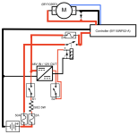
Thank you again for your detailed response amberwolf! I'm back again with a reevaluated schematic based on your feedback.
v2.1.png

We've got 2 switches now. S1 is the pre-charge connection. S2 completes the bypass/primary connection.
Biggest question right now is the pre-charge circuit. I've since noticed that the DC/DC converter has a listed inrush current of 20A@48V and a continuous of 0.8A@48V. All know about the controller is that there are two 63V 470µF capacitors inside. I don't know how to extract anything useful from this unfortunately, even after reading other threads, my brain is a bit fried. Could you let me know if this pre-charge circuit appears safe please, is it OK to have both the controller and DC/DC converter on the same resistor? The risk would be that pre-charge takes too long and the heat is not dissipated quickly enough, causing damage, right? If that's the case, then I should be search for the highest wattage resistor that doesn't create a spark? If I could get some recommendations that'd be greatly appreciated.

I'm forgetting about the ferrite cores based on your recommendations. Thank you for the detailed explanations.

I also need some more time to investigate the flyback diodes. I appreciate the direction with phases etc.

Many thanks in advance
 
Last edited:
The main problem with the DC-DC seriesed with the resistor is that it will take time for it to precharge, too, and the current to it will always be limited by that resistance. If it needs more curent to operate than that passes, then it won't provide the correct output. (aside from potential resistor size/heating issues).

If you use a 2P1T (DPST)**** switch for S1, then you can use one pole as S1 itself, but not connect the DC-DC input to that. Instead, connect the DC-DC input to the second pole's contact side, and the second pole's input side is wired on the fuse side of the resistor. That then bypasses the resistor for the DC-DC, but not for the controller precharge.


****DPST is like having two separate switches ganged together inside one box. What you're using now is SPST (1p1t); where P is poles (independent sets of contacts/paths), and T is throw (only one contact that can be made or broken).


Regarding the resistor value, if you haven't alreayd you can calculate it based on the time you want the precharge to take vs the capacitance of the controller and the voltage of the system; the math/etc is in one of my posts in a thread from earlier this year (I think from harrisonpatm?)
 
The main problem with the DC-DC seriesed with the resistor is that it will take time for it to precharge, too, and the current to it will always be limited by that resistance. If it needs more curent to operate than that passes, then it won't provide the correct output. (aside from potential resistor size/heating issues).
I see, there's an issue here, in that I'm requiring the (restricted) pre-charge circuit to provide the converter enough power to close the relay. Oversight on my part, thanks a million. Would I be correct in thinking that the DC/DC converter would no longer be limited once the relay is closed because the path of lesser resistance will be taken?

Nonetheless though, v2 is flawed 😞 and needs some tweaking, even just to get the relay to close.

If you use a 2P1T (DPST)**** switch for S1, then you can use one pole as S1 itself, but not connect the DC-DC input to that. Instead, connect the DC-DC input to the second pole's contact side, and the second pole's input side is wired on the fuse side of the resistor. That then bypasses the resistor for the DC-DC, but not for the controller precharge.


****DPST is like having two separate switches ganged together inside one box. What you're using now is SPST (1p1t); where P is poles (independent sets of contacts/paths), and T is throw (only one contact that can be made or broken).


Regarding the resistor value, if you haven't alreayd you can calculate it based on the time you want the precharge to take vs the capacitance of the controller and the voltage of the system; the math/etc is in one of my posts in a thread from earlier this year (I think from harrisonpatm?)
Thank you for the explanation of 2P1T (DPST) much appreciated and was an unknown for me. This would remove the DC/DC converter from the pre-charge circuit right? Is 20A @ 48V not something I should be pre-charging?
 
I see, there's an issue here, in that I'm requiring the (restricted) pre-charge circuit to provide the converter enough power to close the relay. Oversight on my part, thanks a million. Would I be correct in thinking that the DC/DC converter would no longer be limited once the relay is closed because the path of lesser resistance will be taken?
Correct.

Whether it will cause any problems with the DC-DC running the relay before the relay closes I don't know.

This would remove the DC/DC converter from the pre-charge circuit right? Is 20A @ 48V not something I should be pre-charging?
How big are the caps in the DC-DC? If they're small, tehre won't be much current for very long during the initial turn on, and precharge won't be required. (ifyou can see the caps in it youc an do the math for how long they'l take to charge and what the current would be).

Controllers may have much larger caps, and mroe of them, and may require precharge to avoid switch damage/etc from the inrush current.`
 
How big are the caps in the DC-DC? If they're small, tehre won't be much current for very long during the initial turn on, and precharge won't be required. (ifyou can see the caps in it youc an do the math for how long they'l take to charge and what the current would be).

Controllers may have much larger caps, and mroe of them, and may require precharge to avoid switch damage/etc from the inrush current.
I haven't purchased anything other than the motor and controller so far, trying my best to plan before spending. So I unfortunately have nothing more than is published in the datasheet for the DC/DC converter.
  • (V,in): 18 - 72VDC
  • (V,out): 12VDC
  • Rated current (out): 2.5A
  • Typical current (in): 0.8A @ 48V
  • Inrush current: 20A @ 48V
  • Spec: https://www.meanwell-web.com/content/files/pdfs/productPdfs/MW/RSD-30/RSD-30-spec.pdf

    There are fortunately many teardown videos on youtube that show the two 63V 470µF capacitors of the controller, so I didn't even have to open it up.

    On to the pre-charge resistor calculation. I'm feeling lost here :( I cannot gain any insights from anything I read. It's like I've got a mental block, but I cannot make the correlation between the math and the examples.

    internal refs:

    external ref:

    There is a lot of information here, some posts go deeper than others, like:

    But I get the impression that, to quote one post; "You can use pretty much anything for the précharge connector.". A lot of people seem to choose 1000 Ohm (I have no reference which explains this) then go with lower Ohm values if there is still sparking when making connections. Another quote: "Try a smaller resistance value, like 100 ohms. It doesn't need to be 10W either, the current inrush is very short, so there shouldn't be much heating. If there is, something else is wrong. A 5w resistor should be plenty big.". Both of these are relating to a 96V fardriver controller inrush, the first internal link above.

    The "diyelectriccar.com" thread linked provides a table with 1000 Ohm resistor @ 48V:
48V / 1,000 Ohms = .048A
.048A x .048A x 1,000 Ohms = 2.3W
There is for sure more to the math than I'm understanding. However, could I make somewhat safe assumptions here that by going with something like the following, that I should have ample headroom even with the 30W DC/DC converter and controller (2x 63V 470µF) inline?
Of course the most recent schematic is still flawed, but for now maybe pretending that there is another switch on the thicker positive cable to the DC/DC converter which must also be moved to the other side of the relay (before, not after the NO connection). Which must be turned on before S2. So ordered:

  1. S1, pre-charges controller & DC/DC converter​
  2. Imaginary S on positive to DC/DC converter before relay, powers DC/DC converter (and potential ancillaries), closes relay​
  3. then S2, powers controller & motor​

Again, thank you very much to taking the time to read, respond and explain these things to me. It's wonderful that people are willing to do this just because they can. I really appreciate it. Many thanks.


Edited later: I'm going down the math hole a little more. Kind of thinking out loud and trying to make sense of things. Apologies in advance 😅

For the pre-charge there might be some useful values I can get.
Charge: Q = CV
Energy: W = ½ QV = ½ CV2

Using 54 as the voltage (54.6V max full charged and healthy 48V nominal battery) and assuming that the capacitors cannot be charged above the input voltage, at least significantly.

This gives the following for the controller (using 940µF)
Charge Q = 50.76m Coulombs
Energy W = 1.371 Joules

I'm not sure if this is useful though. Or if the inrush from DC/DC converter can be used to calculate the energy requirement. Then also not sure if the energy is useful.

Doing more math :) Adjusting the wattage calculation above in quotes.

@ 1,000 Ohms:
54V / 1,000 Ohms = .054A
.054A x .054A x 1,000 Ohms = 2.916W

and again at @ 150 Ohms:
54V / 1,000 Ohms = .054A
.054A x .054A x 150 Ohms = 19.44W o_O

Taking precautions for similar load (Wattage, does this make sense?) from the DC/DC converter I could put: ARC HS50 150R F
I need to stop here, getting a bit overwhelmed. If you make it this far, thank you and apologies! 😅😇🙏
 
Last edited:
I haven 't gone thru all the math yet, but note that the power peak of the current for precharge only lasts for a very short time, and rapidly (exponentially?) drops as the current drops and the voltage drops. So you don't actually need anywhere near as big a resistor as you'd think, as it only has to handle the power dissipation of a pretty small amount of heat, realistically.
 
I haven 't gone thru all the math yet
I can't say that I blame you. Thanks for your support all along the way to date.

Honestly, the more I look at it and read anything related to pre-charge, the less I understand :( I searched a little more last night and I'm still at a total loss. Is there some kind of "rule of thumb", like if I go for 150 Ohms and the highest possible wattage handling I can find, (50W or upwards) that I should be on the safe side?
 
Last edited:
I can only re-suggest reading my more-recent previous posts on the topic that go thru everything step by step. Sorry I don't have a link, but should be in the previously-suggested thread(s).

The amount of resistance needed is dependent on how long you want precharge to take, the maximum current you want to flow, the capacitance of the device(s) being precharged, and the system voltage, so there is no "safe" rule of thumb possible; all of those things are too variable.

Wattage of resistor you can use as big as you like...it's just a waste of space weight and money in almost all cases. ;)
 
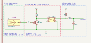
Connecting a three wire brake (hall) sensor to a two wire KT controller input.

To be on the safe side, I made up this small circuit to connect my (hall) brake sensors (photo below) to my 2-wire KT controller input.

I connected the VCC of the small circuit to the Throttle power (4.3V)
Works very well, I'm happy!

Improvements are welcome, I am not an electronics expert as you can see.

1701335653415.png


ebike brake sensor.png
 
FWIW, you don't need any of the electronics. Just wire the brake sensor ground to controller ground, the brake signal to controller signal, and the sensor 5v input to the controller 5v.

Hall sensors like those used in these HWBS-type brake switches (all the ones I've seen so far, anyway) and in the hall-type ebrake levers, are used like those in motor sensors--they have an open-collector output (that has a pullup resistor to 5v, internally to the sensor unit or inside the controller, or both), that grounds the output when active, and opens the circuit when inactive, just like the two-wire kind.

Won't hurt anything to have the electronics you've got there, but they're not necessary. ;)
 
Back
Top