Arimhan said:
I could completely bypass the bms and let the controller handle the low-voltage cut-off but I prefer more security.
you probably actaully want both.
the bms is not really an everyday shutoff; most of the ones i've seen posted about and encoutnered myself have such low lvcs that they basically run the cells to completely dead before they shutdown, which is hard on the cells.
if it's not programmable to bring that up higher, then the controller lvc is usually preset (or programmable) to an lvc that's more like 80-90% empty, which is easier on the battery, and doesn't age it as fast, and tends to let it stay balanced better (depends on the quality of the cells to start with, and how well-matched they were).
so you have teh bms and the relay system to shut off the pack as a last-ditch "dont kill the cells", and the controller lvc as the everyday "oops the pack is low, stop now".
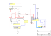
regarding doing everything with a single contactor (presumably operated by the keyswitch): you can use a dpst (doulbe-pole single-throw) type, so you have two separate electrical paths, both of which turn on / off at the same time. (a dpdt can also be used but you're never using the nc contact so no point in spending the money on that, and they're sometimes larger and heavier so wasting space/weight too. )
the keyswitch will need to be a spring-loaded type, like a ice-car's starting keyswitch, so that it returns to "run" after being turned to "start", so it cannot interfere with the bms's ability to shut the system off. but it needs another set of contacts in the "run" mode, that close the connection between the bms's discharge output connection (p-?) and the relay's coil. so the keyswitch is also a two-pole single-throw type, but one that has a constant "run" connection, and a momentary "start" connection, if that makes sense. i can see what the contacts inside would look like, i'm just having a hard time explaining it.
the keyswitch's "start" contacts would be wired in series with a large resistor (say, a 10watt sized 1ohm resistor) and create a circuit *across* the n.o. and common relay contacts of whichever circuit will create current thru the coil to keep it on. you might actually need a third contact set (3pst) for this part, whose nc contact goes to battery positive, and whose common contact goes to one end of the coil, then the coil goes to p-. i am having troulbe thinking clearly enough to draw it out but it's easily done. look up self-latching relay circuits and you'll see what i'm talking about.
(if you can't find a keyswitch with this function, you can use a regular two-position (off / on) switch for the "run" / off switch, and use a separate pushbutton momentary spst n.o. switch for the "start" switch; a number of motorcycle handlebar control clusters already have such a switch, and sometimes also a "run/stop".
so the relay coil for the upper-left relay would be wired in series with the common contact and "run" part of the keyswitch, rather than powered constantly as it is now.
so the way it works is that there is no circuit at all until the keyswitch is pushed past the springloading to short the coil on. the resistor in series with teh switch slows current flow enough to not damage the keyswitch contacts, until the coil has enough current flowing to switch the relay contact that then shorts across the keyswitch and resistor. you can size the resistor experimentally if necessary to make it the right ohms for just a quick twist of the key, so you don't have to hold it very long (like a second or less). might not need to be as high a wattage either, you can calculate that out by the resistance and voltage in the circuit.
the idea is that the relay self-latches itself on during the initial keyswitch pulse, so everythign stays turned on after this. but the bms will shut off the relay if any pack condition it's setup to turn off for occurs, or the keyswitch is turned from "run" to "off", as either one of htose breaks the relay coil's circuit from b+ to p-.
the relay coil for the rightside relay no longer exists; it's now just the coil in the upper left relay, as these are both in the same contactor if it's dpst.
does all that make sense?
totally separate from that, and off-topic for this thread:
...if all you have is a 500w middrive, it's not going to be much of a motorcycle. if it's a motorcycle frame and wheels and such, it's going to be so heavy that it's likely to take you a long long ways to get up to speed from a stop, unless you have a transmission you can shift down to high torque for startups, then to lower torque and higher speeds as you get faster....but it is still not likely to get past around 20mph or so, unless it is a fully-faired recumbent type.
if the battery and drive size is just because it's the test bed for the future project, then the above isn't an issue.

just that your original post's wording describes this as a low-power ebike, a test bed for a full blown electric bike, and mentions regulations for a street-legal motorcycle, so it's a bit confusing to me (especially since there's still too much blood in my caffeinestream right now). :?
if you would like to discuss this part of the project, please start a build thread over in the motorcycle section, and post a link here in this thread, and i'll follow you over there to figure out what it will actually take to do what you want (whatever that ends up being).


![cr_s104.250.sn[1].png cr_s104.250.sn[1].png](https://endless-sphere.com/sphere/data/attachments/187/187252-6edfa2503f59a41f4e80dab037cc4845.jpg)
![710YCg00HwL._SY256[1].jpg 710YCg00HwL._SY256[1].jpg](https://endless-sphere.com/sphere/data/attachments/187/187253-89e8eea546f1a438e0b3a029e1d858c7.jpg)
![71VkhgXtscL._SY256[1].jpg 71VkhgXtscL._SY256[1].jpg](https://endless-sphere.com/sphere/data/attachments/187/187254-c1a2162702a0186fc10787fb32595e27.jpg)