MorbidlyObeseKoala
100 W
- Joined
- Apr 6, 2018
- Messages
- 168
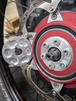
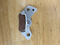
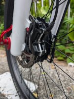
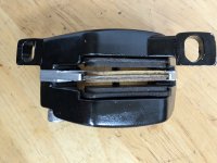
That is a really cool solution and interesting test info.The only safe and practical solution was to mount a small hydraulic brake (from a 1/5 rc model car) plumbed into the main brake line using the bleed port from the main caliper. The 80mm aluminum rotor is connected to the clutch planet carrier thru a hub.
How is your pad life now that you have the braking performance you require?
")