Z000 Amateur
1 mW
- Joined
- May 27, 2019
- Messages
- 11
Hello! I just finished up my Kawasaki Z125 conversion and I wanted to share it with yall. This forum was super helpful for ideas and info during the build.
Here was my totally stock Z125 Pro (excpe the bar end mirrors).
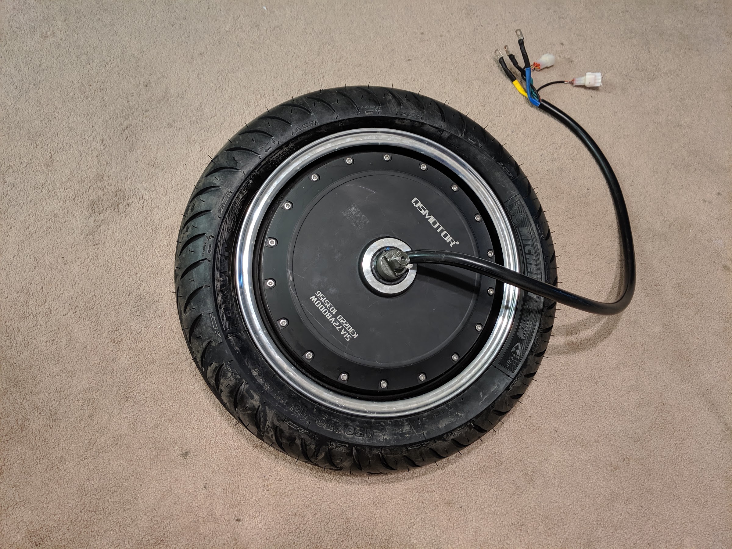
This is a small bike so I decided to go with a hub motor to conserve space. I ended up selecting an 8kW QS hub motor and a Kelly KSL-7275H controller. This system runs on 72V.
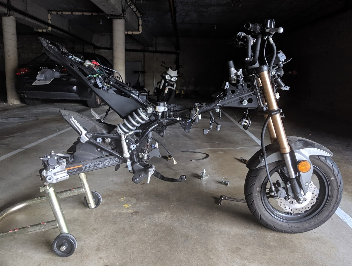
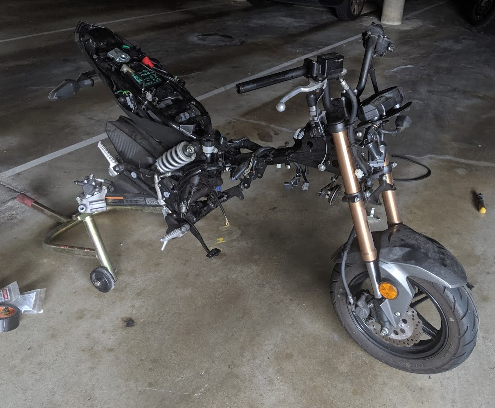
Next, I got rid of the engine. Sorry for the pictures in a dark garage. It’s a shared garage for the building and the landlord has the lights come on at night on a timer. That means it is always dark.
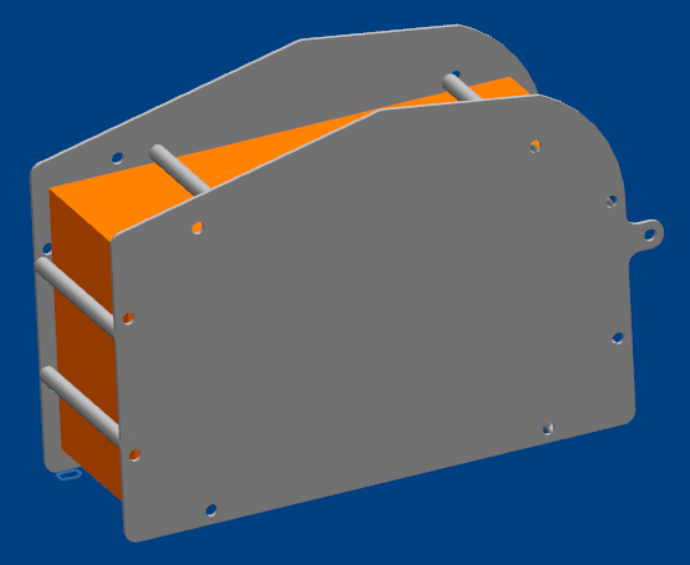
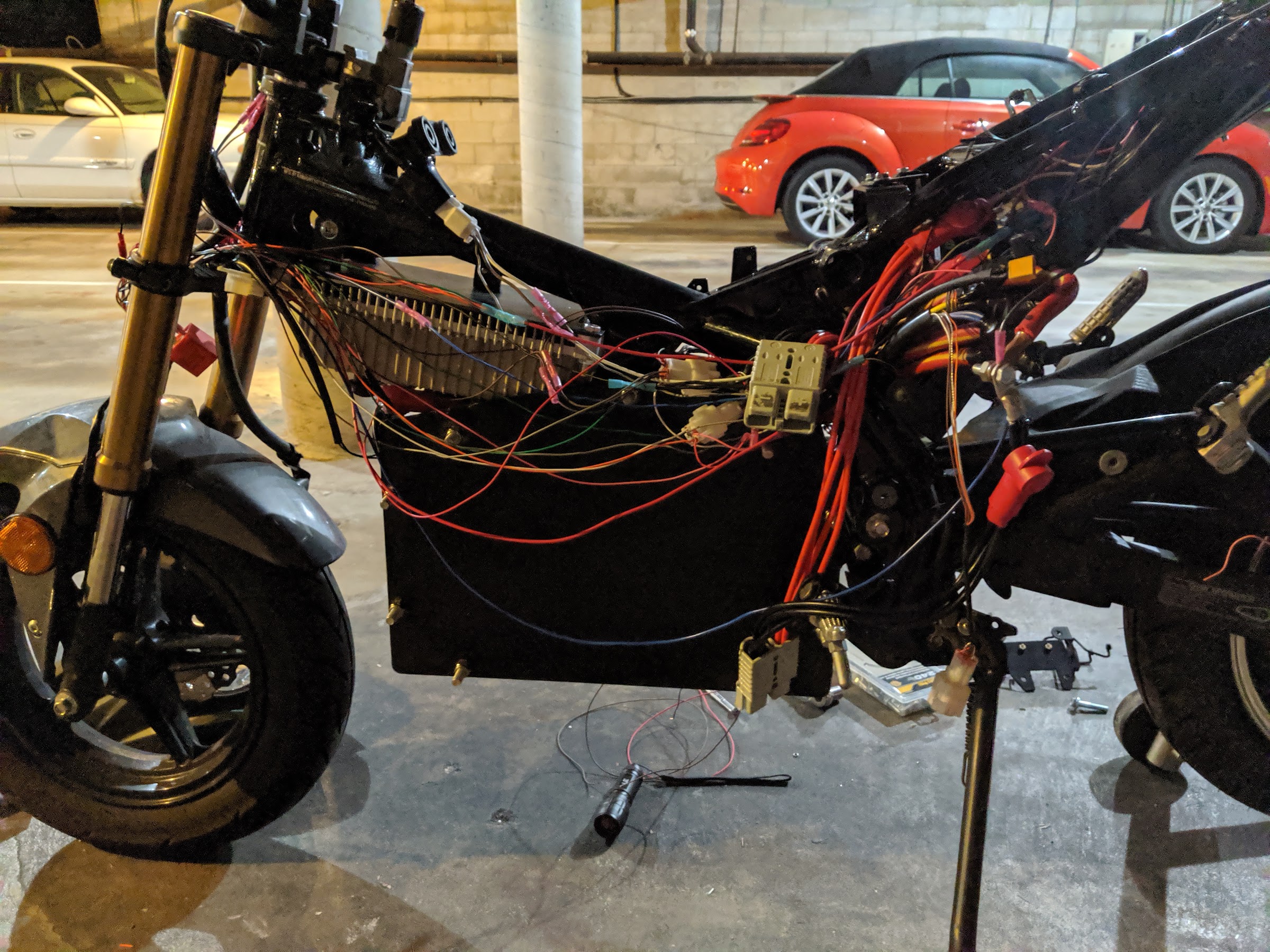
Since the hub motor doesn't take up any space the entire engine area is wide open for a decent size battery. Since I’m not a good welder trapped the battery between two plates separated by spacers, with closeouts around the outsides. I modeled it up in CAD to create a file for cutting the plates.
Next step was motor testing. Unfortunately I didn’t take any great pictures of this setup, but maybe that’s for the best so you don’t have to see how messy my bedroom is. I had the wheel/motor on my rear stand and then a rat’s nest of wires between components. This is all temporary and I cleaned everything up before installing on the bike.
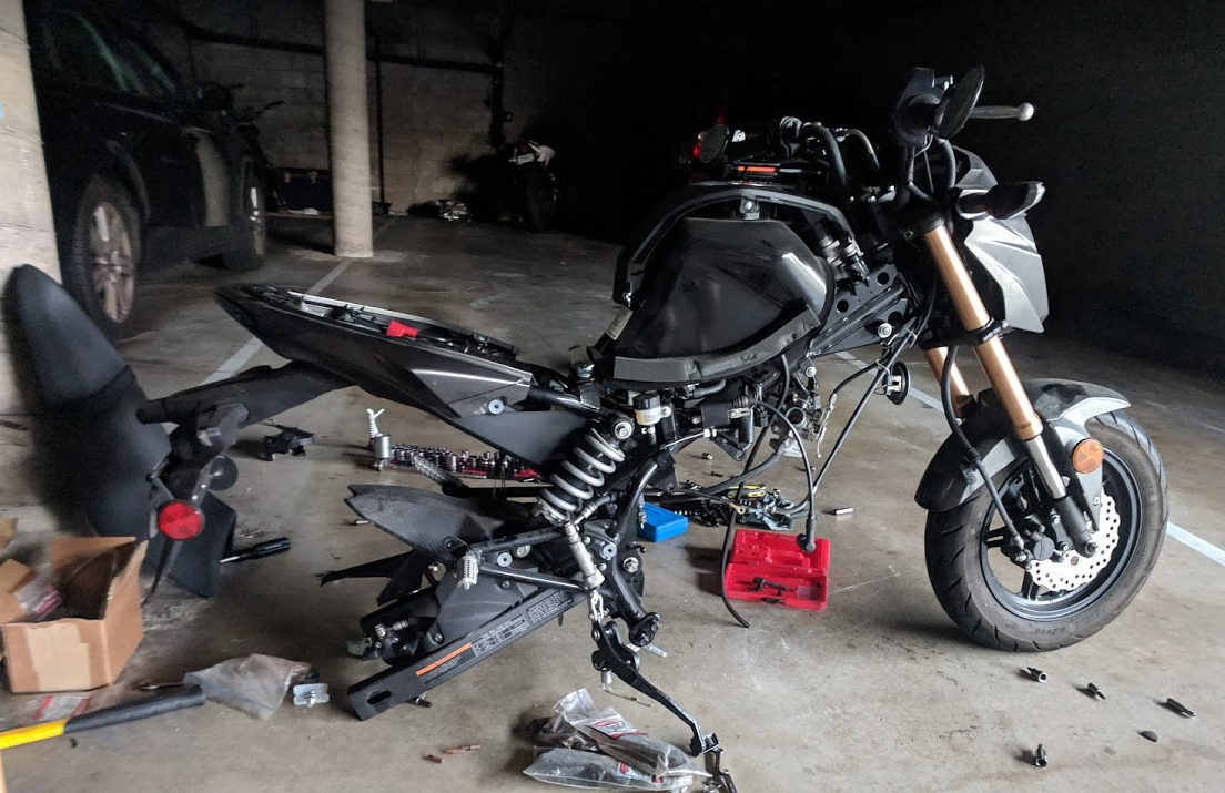
I still had a bunch of gas guzzling parts on the Z that needed removal. I took off the grips, fuel system, tank, clutch lever and associated hoses and wires. Now we’re at bare bones. Extra fuel was donated to my Triumph (in the background) which happy drank it up that week.
Next I wrestled the tire over the wheel.
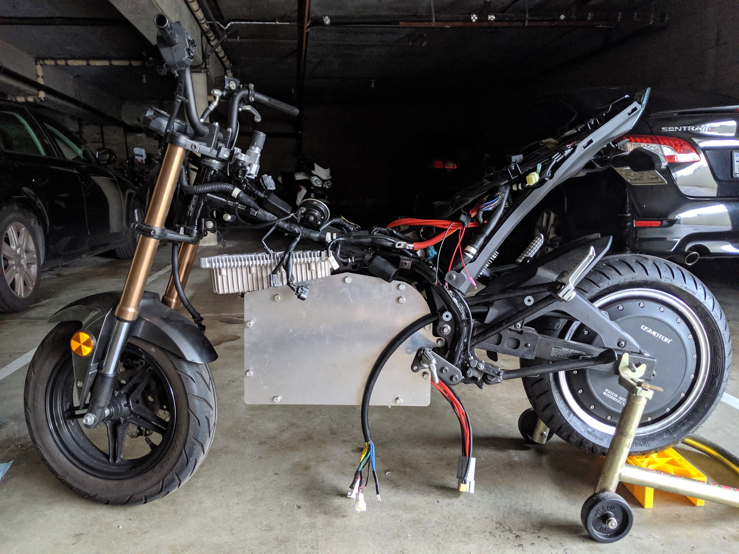
After that, I got everything mocked up on the bike. Overall I like how it looks! The battery fits really well (mounted to the old engine mounts) and doesn't really look all that out of place. The controller is a really tight fit on top. I took some measurements during this mockup install to make some brackets for the controller. I also needed to relocate the horn since that goes right where the controller is sitting.
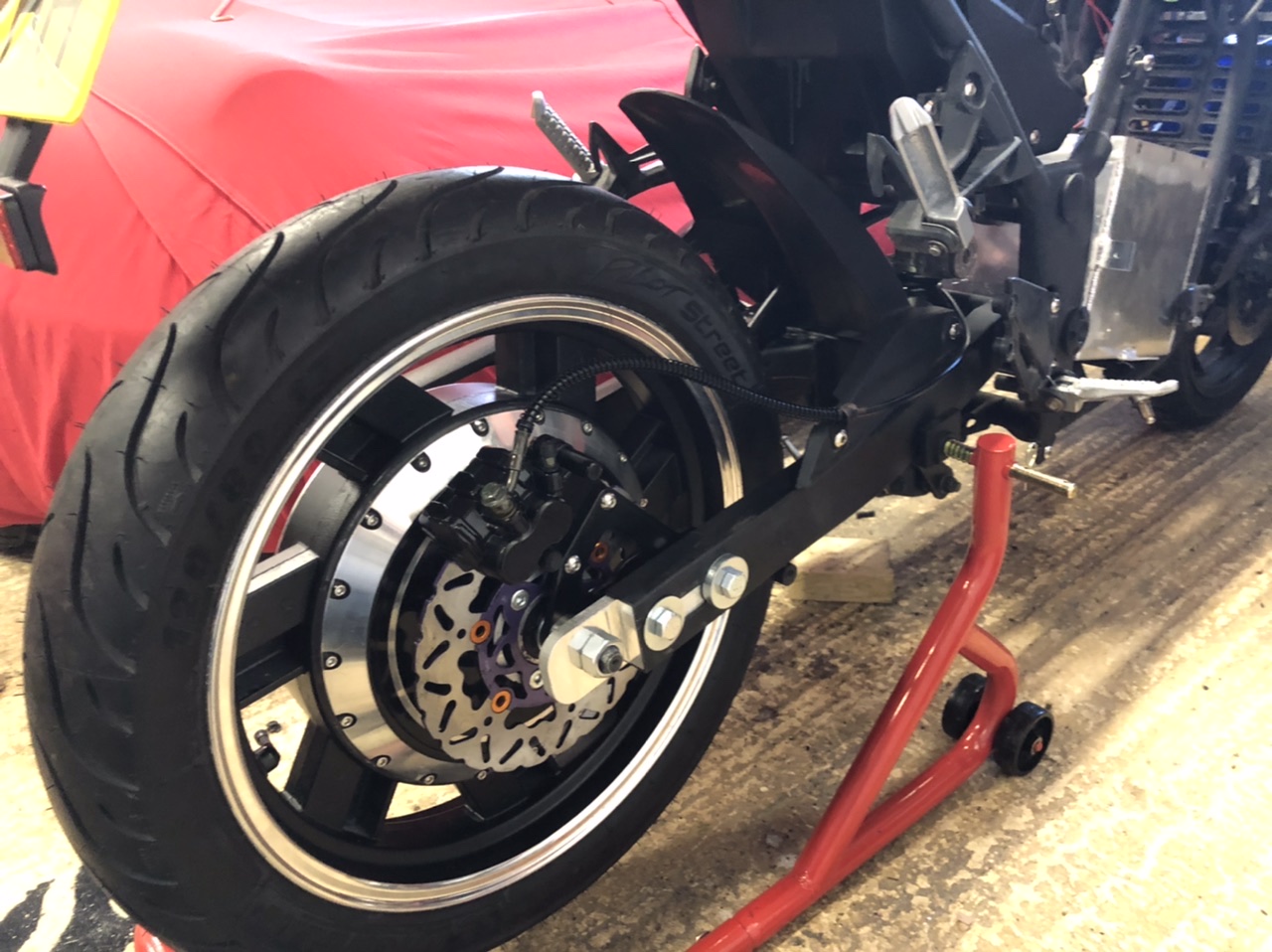
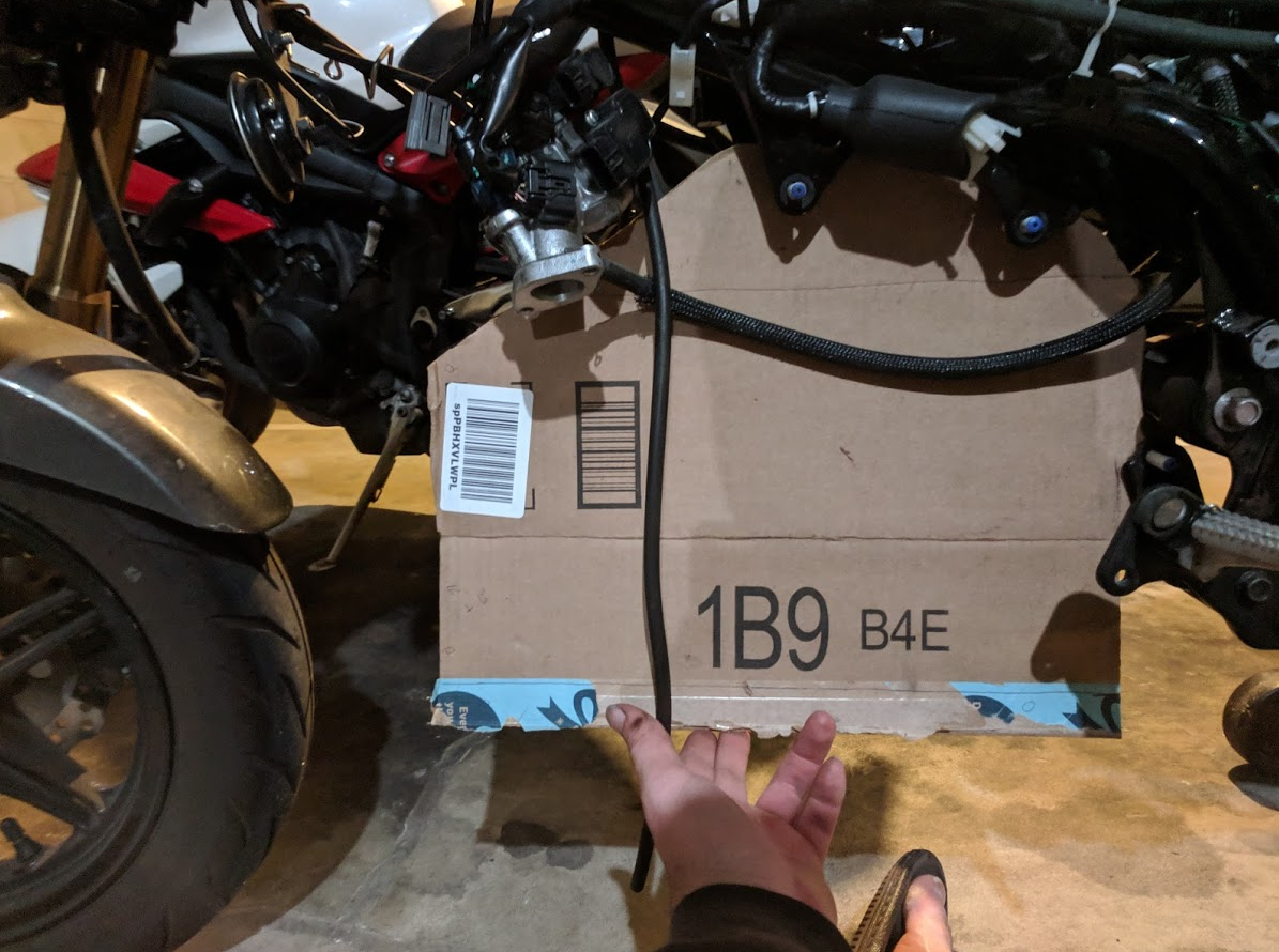
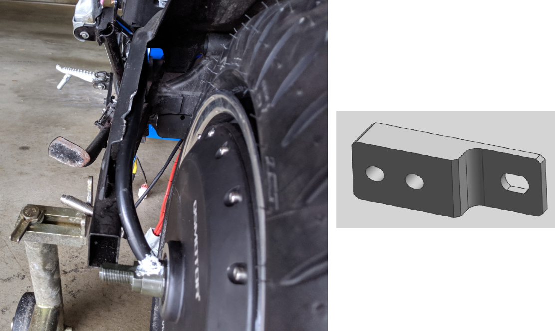
The wheel/motor will sit slightly behind where the stock one was. I made plug that goes into the back of the swingarm and provides the slotted mount to hold the motor axle. The cable bundle from the motor runs up along the inside of the chain guard toward the controller.
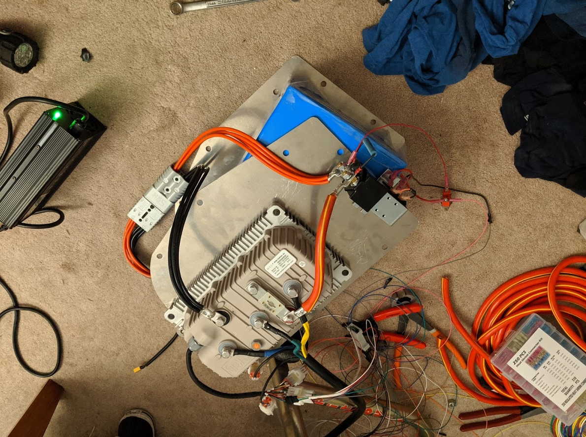
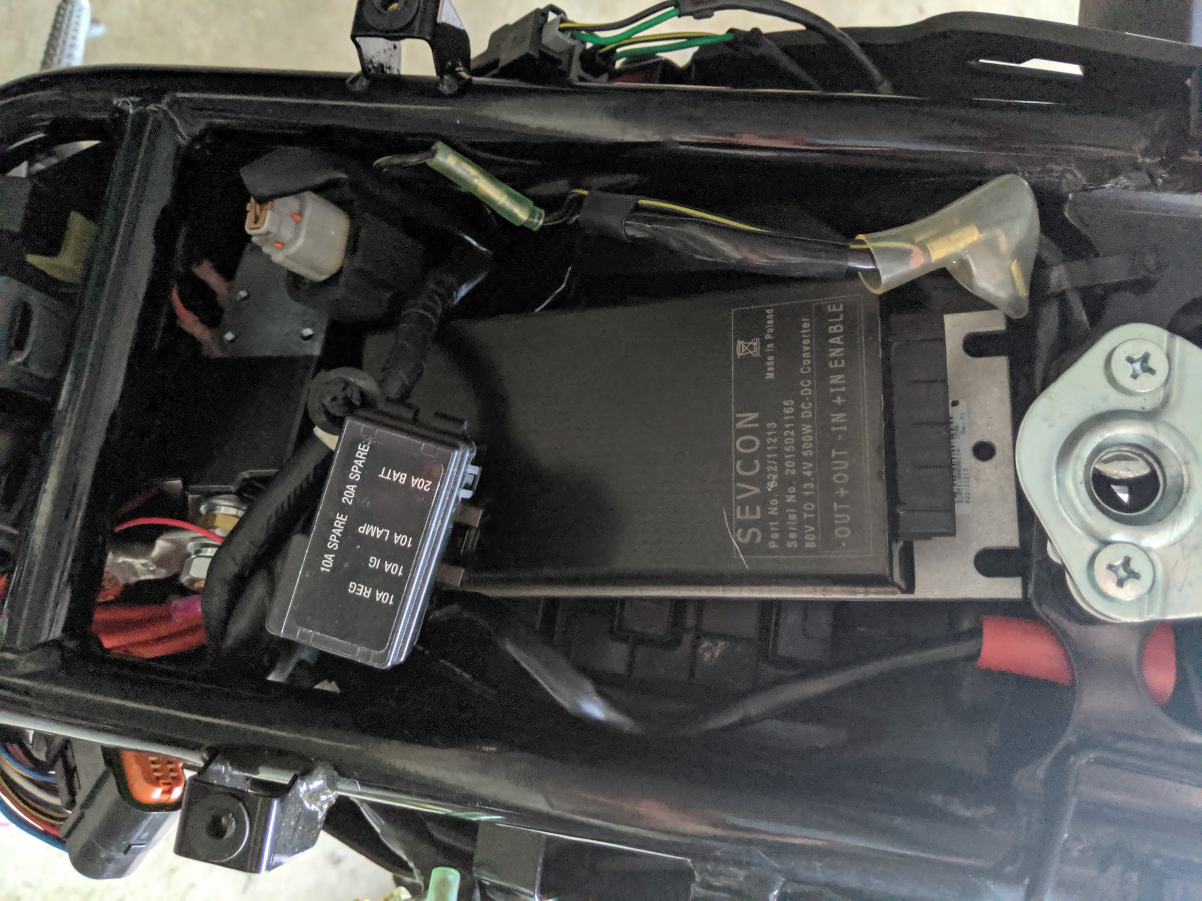
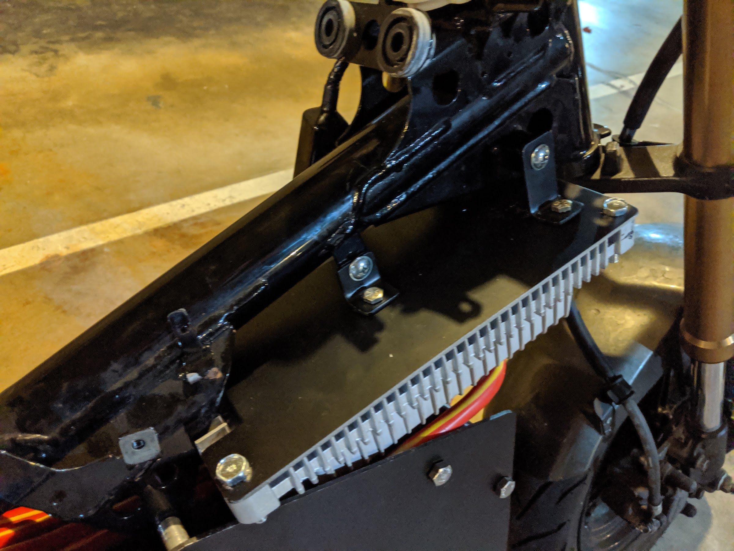
Once I took the battery and ECU out, the DC-DC converter (72V battery step down to 12V to run lights and gauges) and the main contactor fit in there.
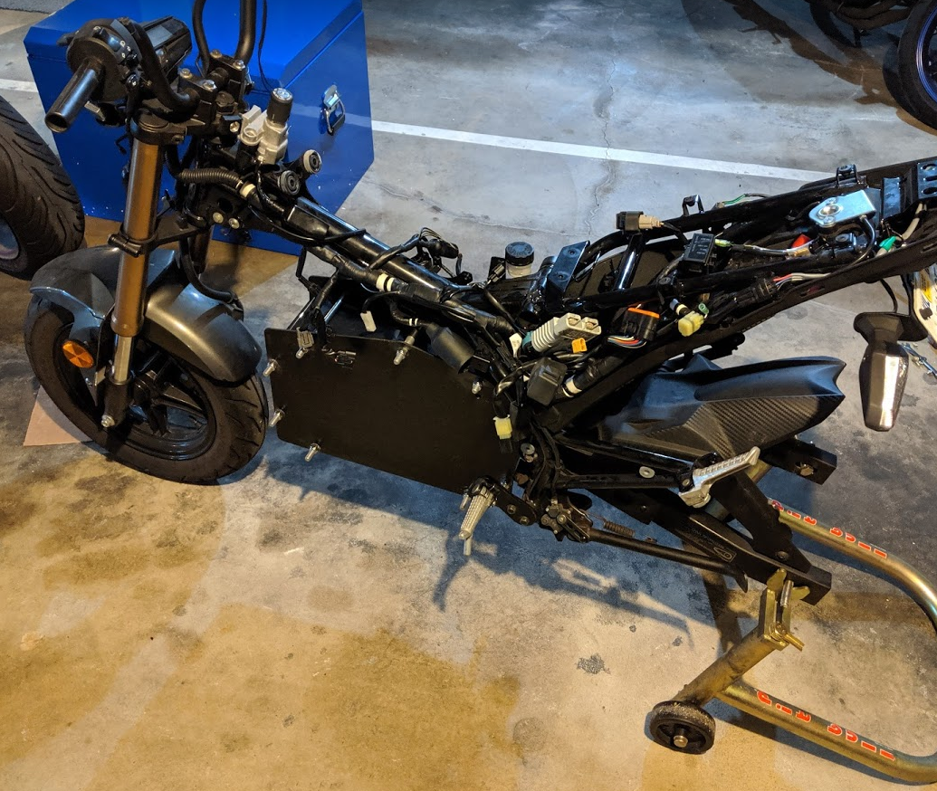
I painted the battery box black, then added a strip of black plastic around. This looks a lot better than bare aluminum and the blue battery plus I think the plastic will help protect against small rocks and debris kicked up by the front tire.
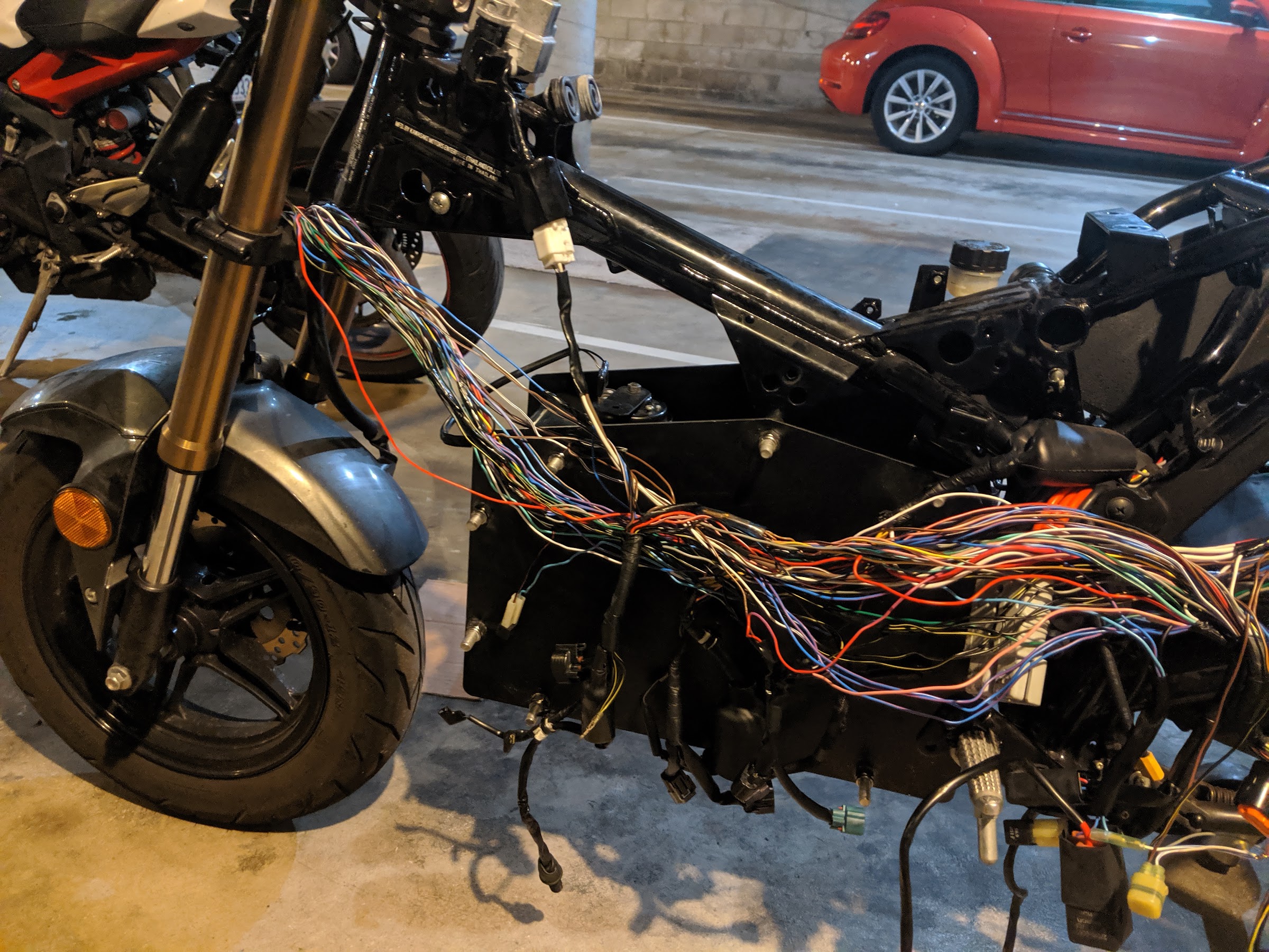
Things were getting a little tight with the new components so I also freed up some space by getting rid of the unnecessary wiring. There are a whole lot of wires once I cut the harness open and I really gave those Harbor Freight wire cutters a good workout. I even got a little too snip-happy and cut off the horn (oops). The only thing I really wanted to keep was the lighting circuit. However, it turns out everything runs through the speedometer so once I got rid of that I needed a separate standalone flasher relay. It works now and I reduced the the wiring by a lot.
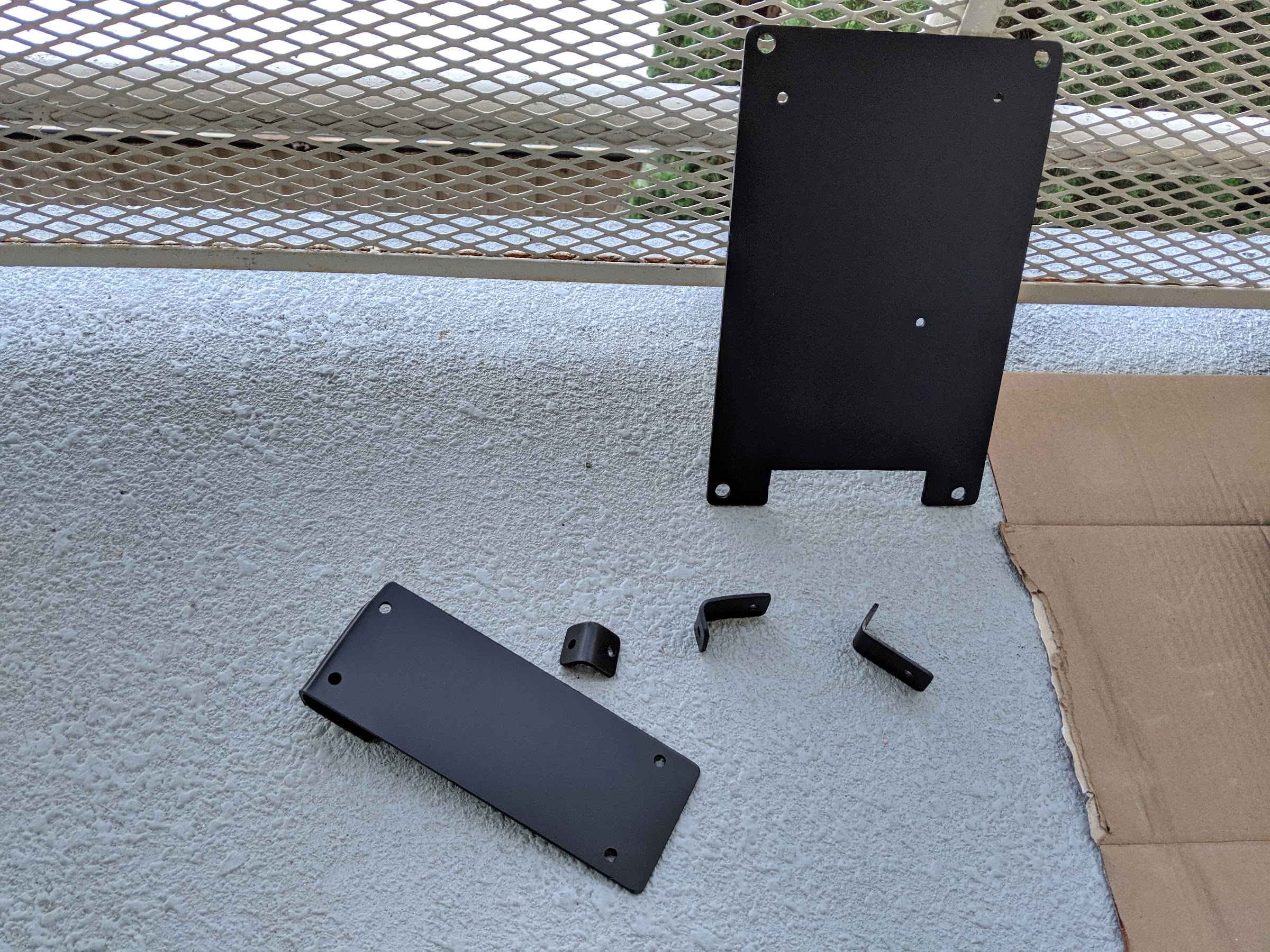
I figured out some brackets once I had everything mocked up and cut them out of aluminum. I don't have a lot in the way of tools and workshop space so everything takes longer than it should.
The controller packages tightly right above the battery and picks up the old airbox mounts. There is barely any space with steering at full lock, but it does fit.
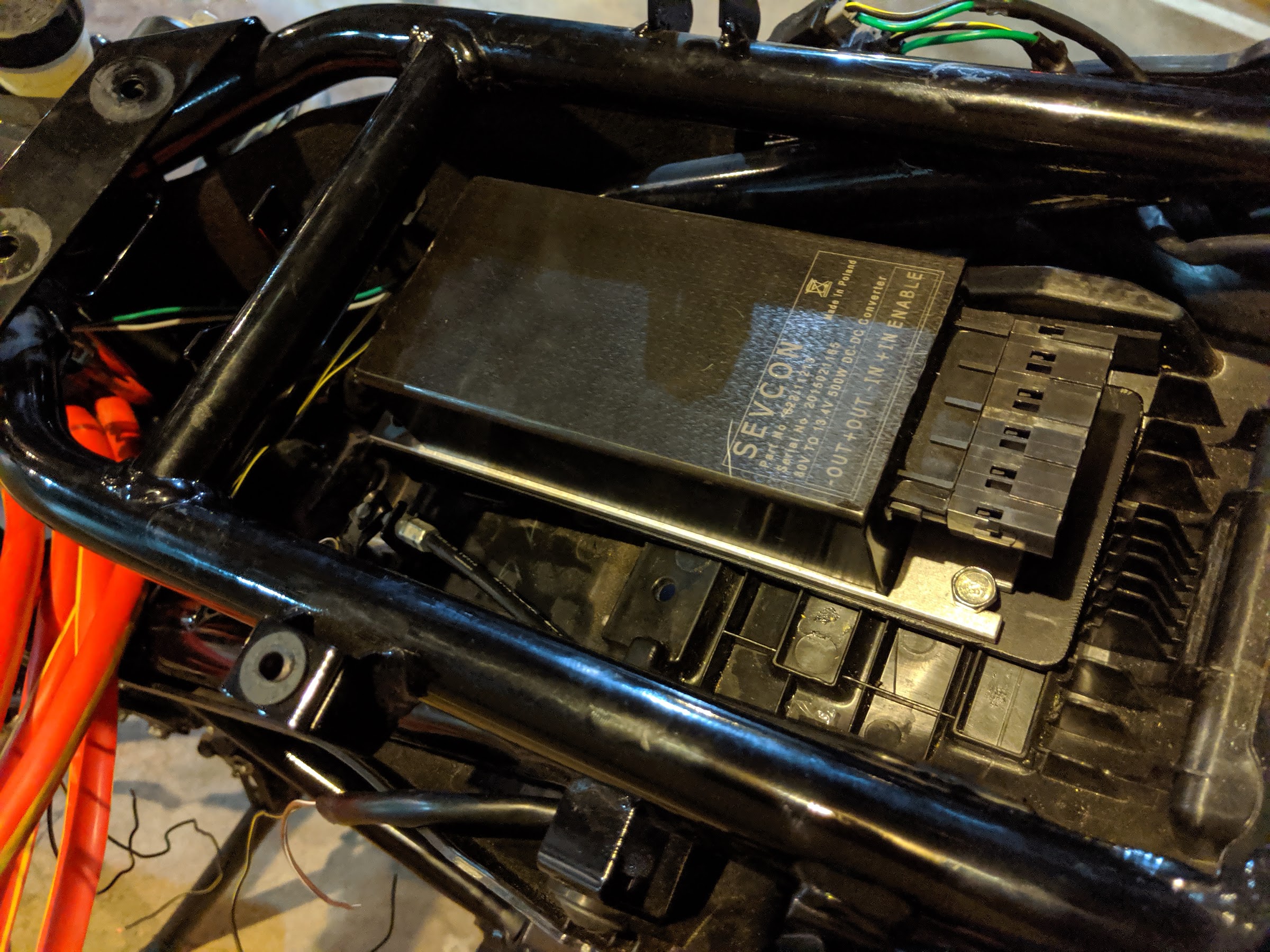
The DC-DC converter goes under the seat, where the battery used to be.
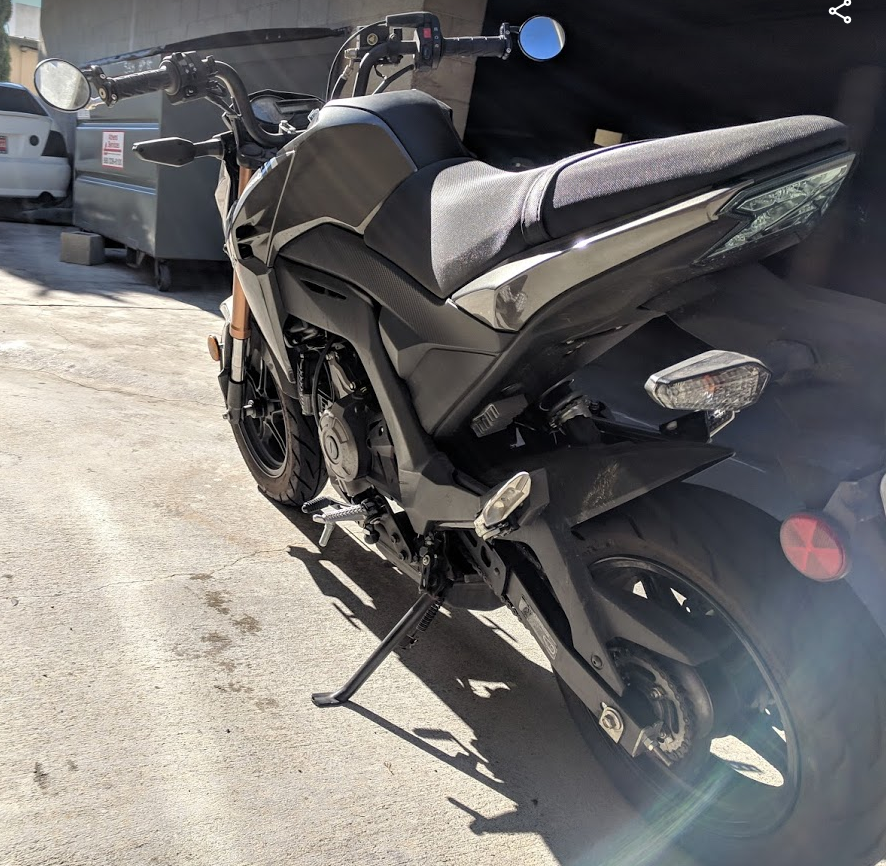
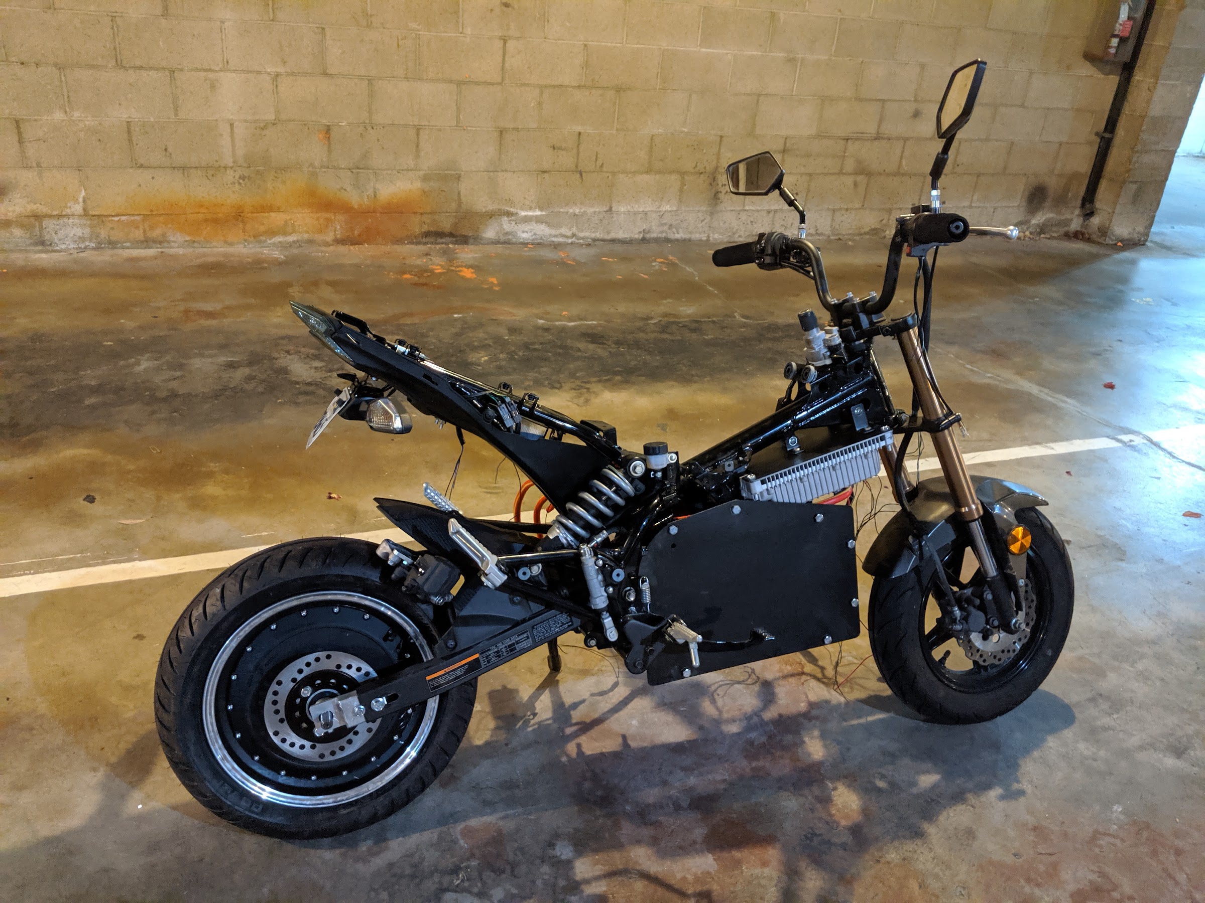
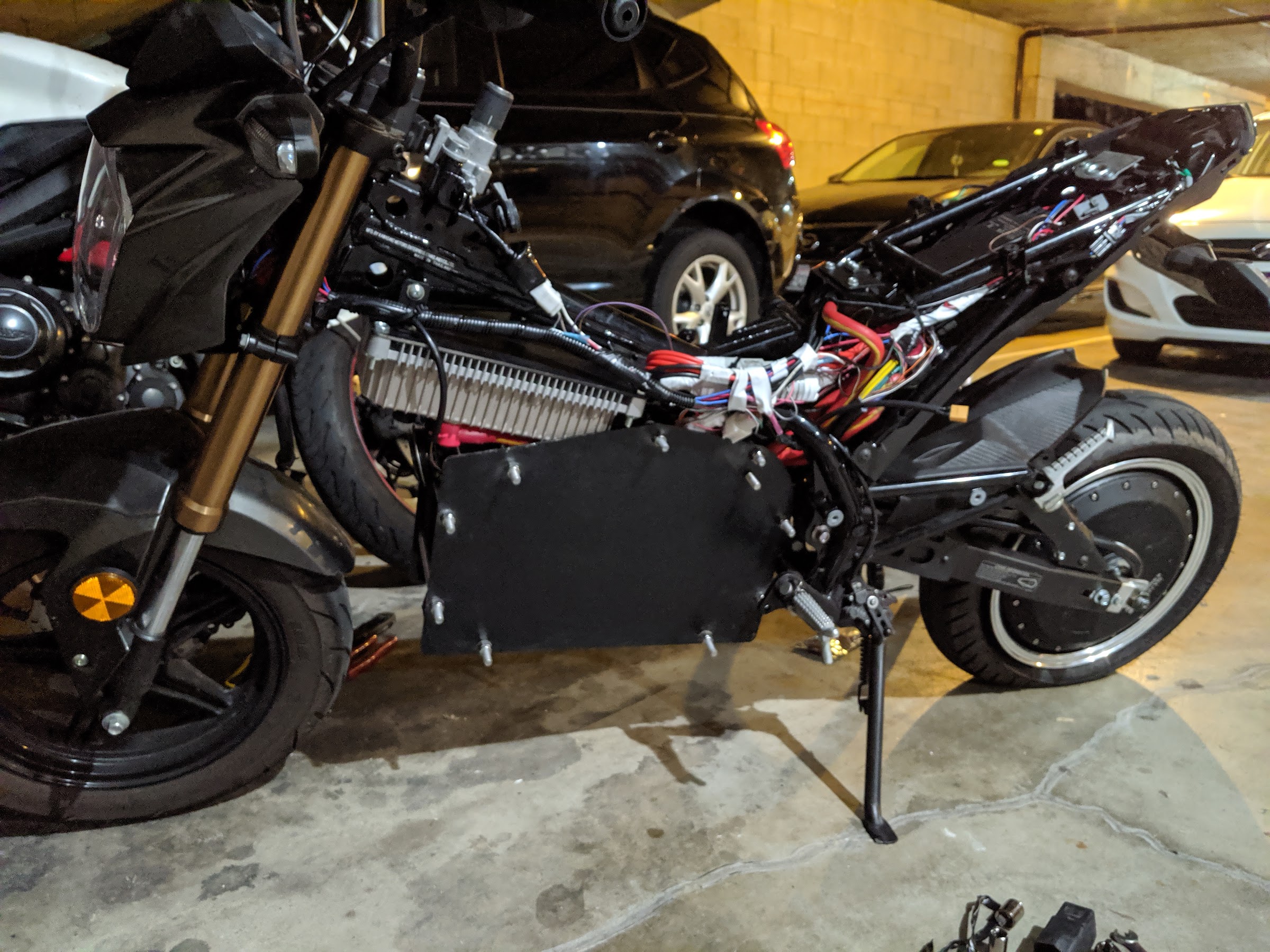
The bike looks super clean from the right side after installing the wheel/motor. Finally back on the side stand! I also installed the throttle and mirrors.
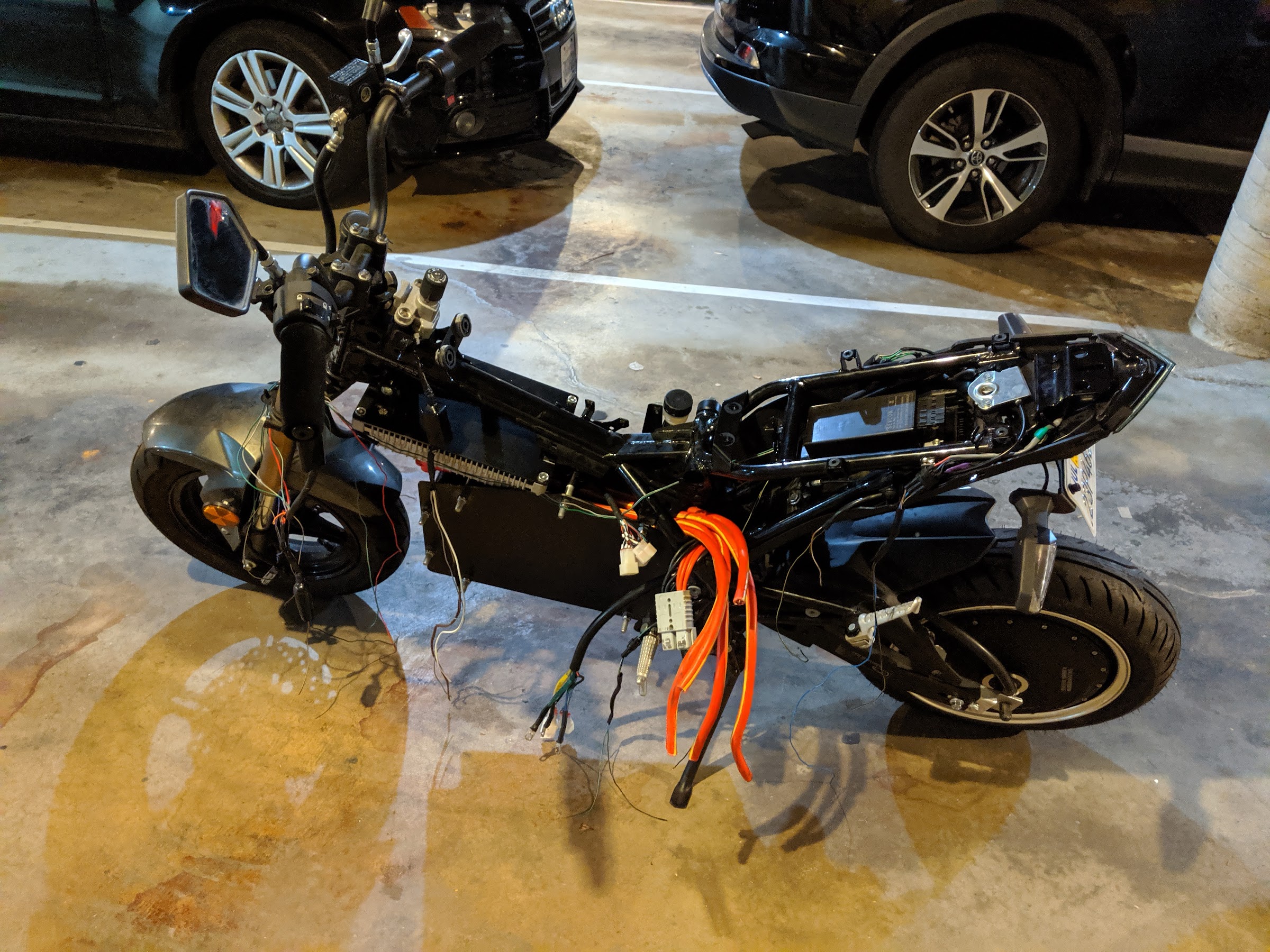
The wire extensions coming out of the controller are comically oversize since I only bought a few different wire sizes.
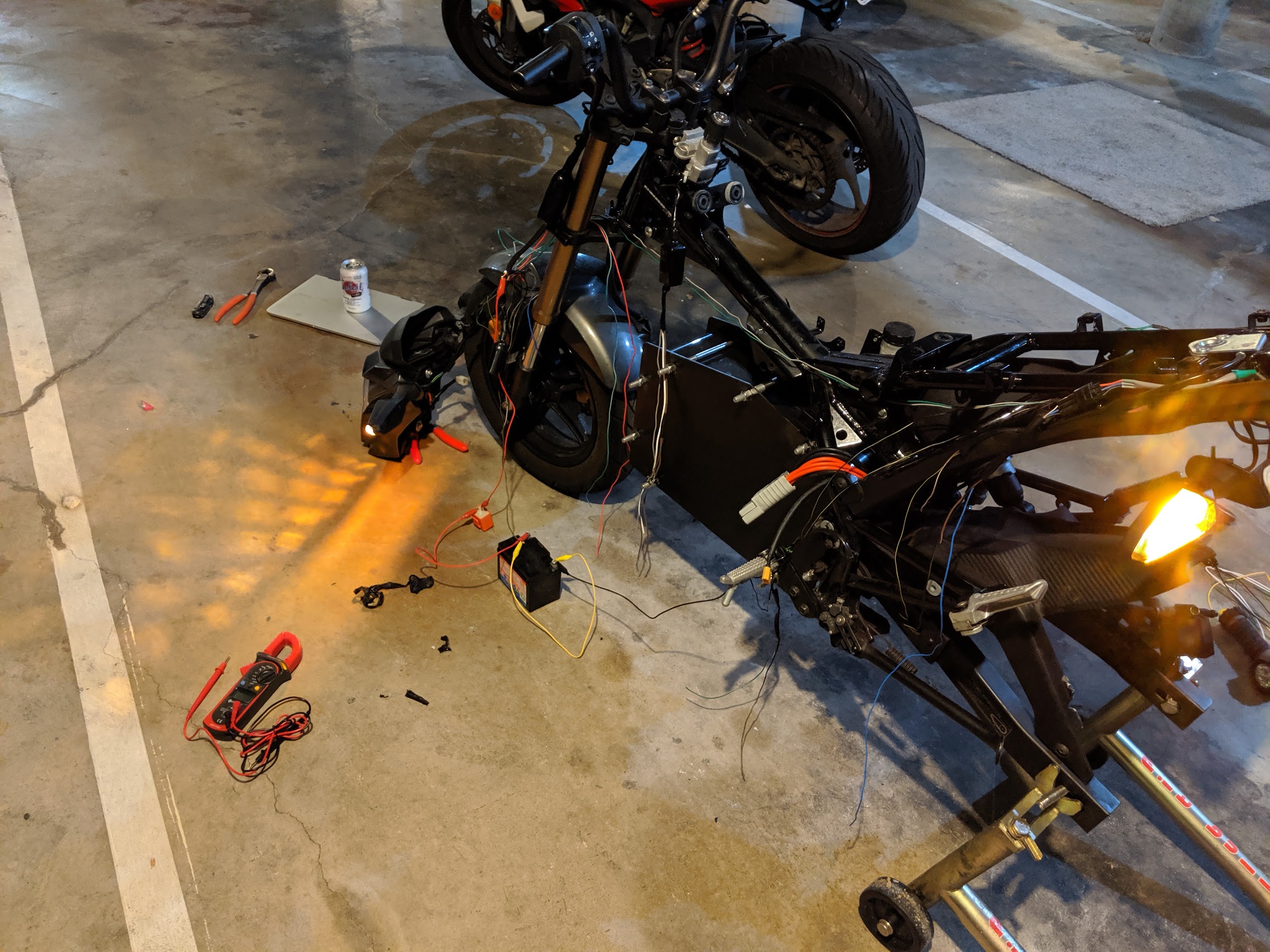
Next I trimmed all the wires and connected everything up, both the high voltage and low voltage (lighting) circuit. I also got the speedometer working and calibrated.
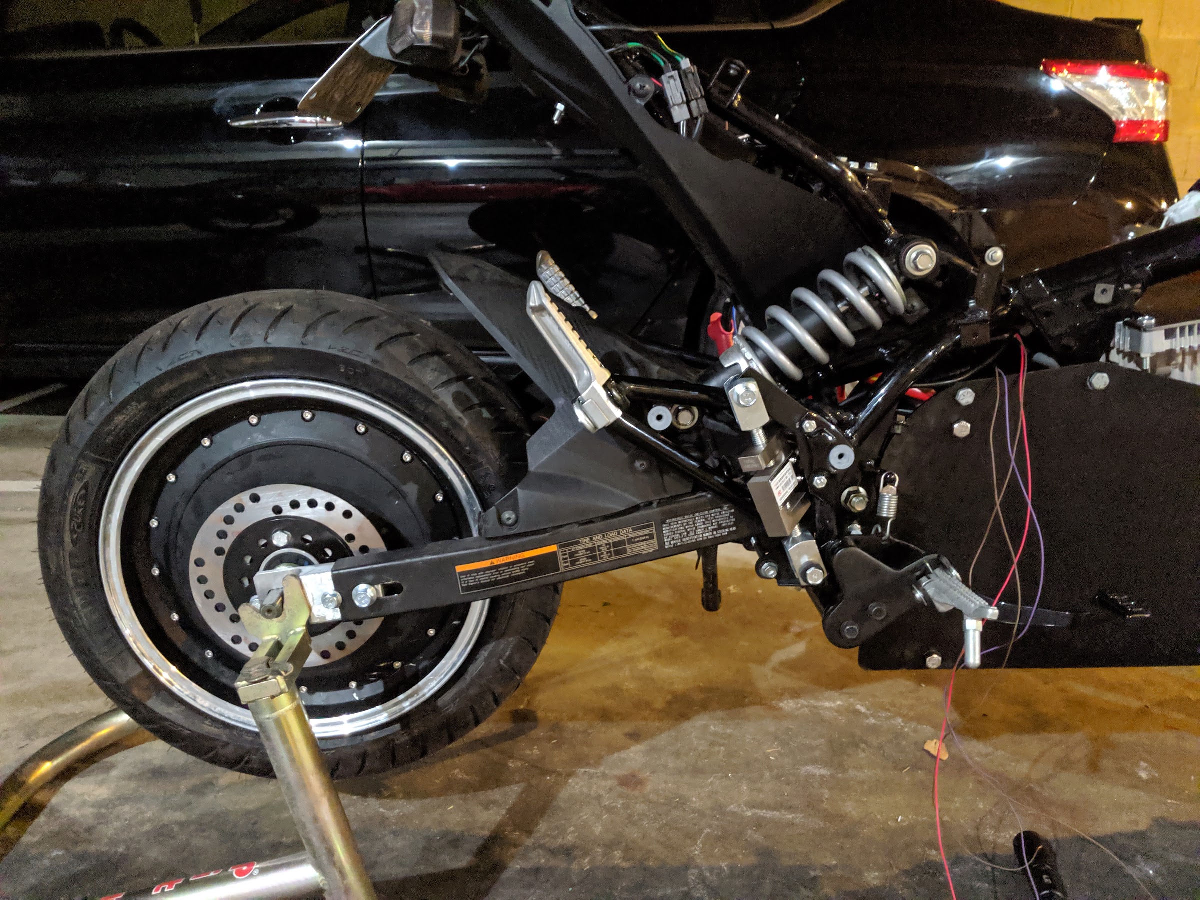
For my rear brake, I'm ditching the mechanical brake in favor of regen only. I figure emergency stops pretty much all come from the front tire anyway, especially with a wheelbase this short. The motor controller accepts a 0-5V signal for variable regen so I am getting this signal with a load cell. I mounted the load cell using a custom bracket off the rear brake master cylinder tab and the other end goes to the brake pedal. Since I think a fully rigid brake pedal would feel weird, I used rubber bushings in the mounting holes so there is a tiny bit of compliance like a real brake pedal. The output from the load cell runs through an amplifier to get the 0-5V signal for the motor controller. This turned out fantastic, braking feels really good and just like a firm conventional brake pedal.
I bundled the wiring a little better (still not super neat honestly) and then went for a test ride! Woohoo!
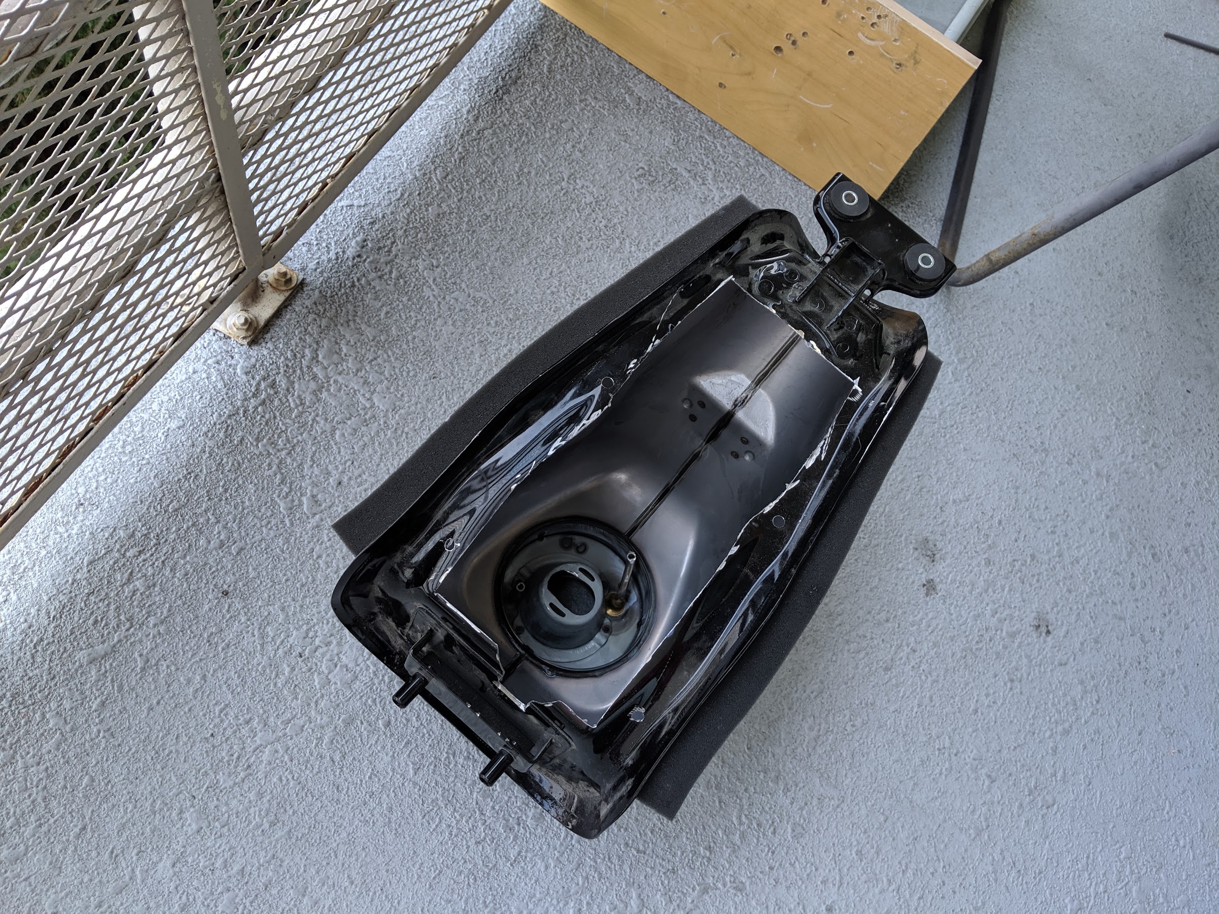
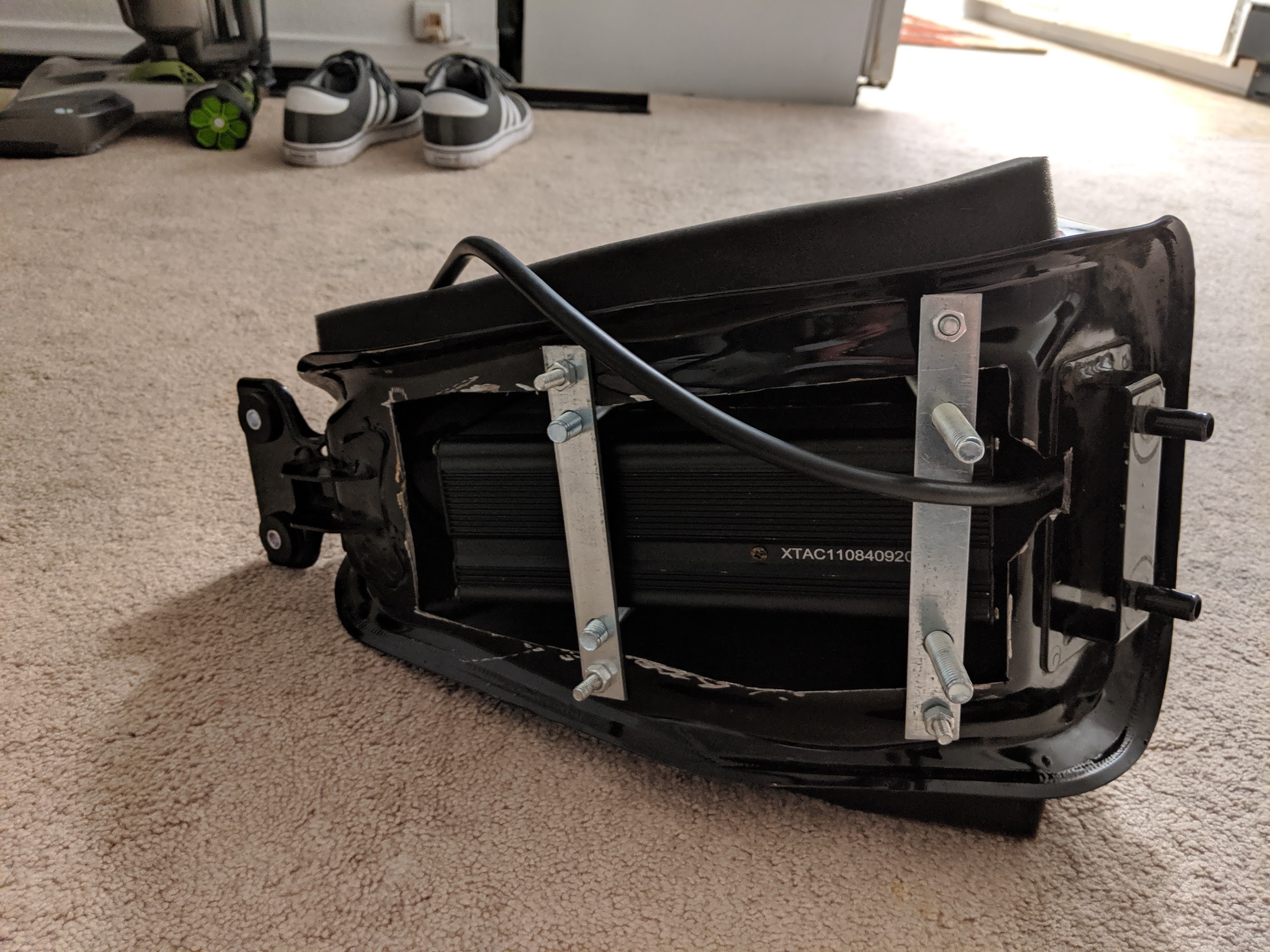
Next I got to work on the onboard (tank mounted) charger. First I cut a hole in the bottom of the tank. There is lots of open space to make sure I have good ventilation.
The charger fits inside (barely) and is fastened with square U-bolts to a bracket spanning the opening. For the picture, everything is in there temporarily since I wanted to add some foam padding where the U-bolts clamp and add trim around the edges to avoid cutting the wires. I cut off the excess U-bolt length after that too.
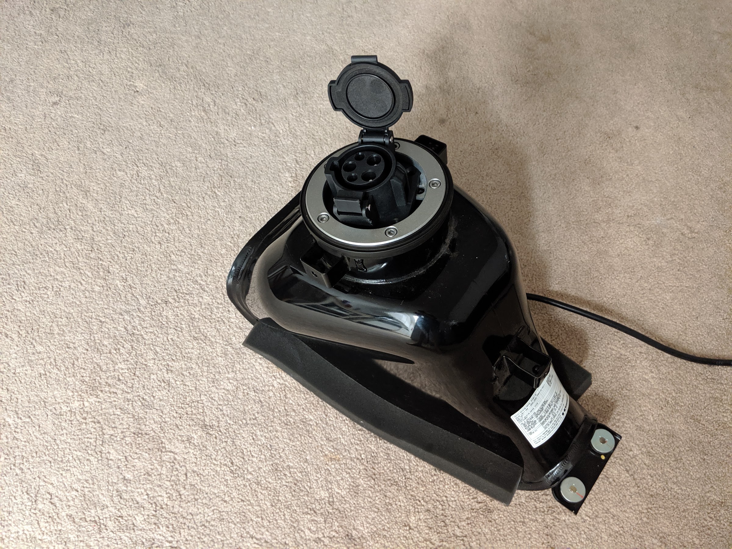
I like how it looks from the other side. This is a J1772 connector which I have at the charging stations at my work. I was able to fit the stock silver trim ring around the plug housing.
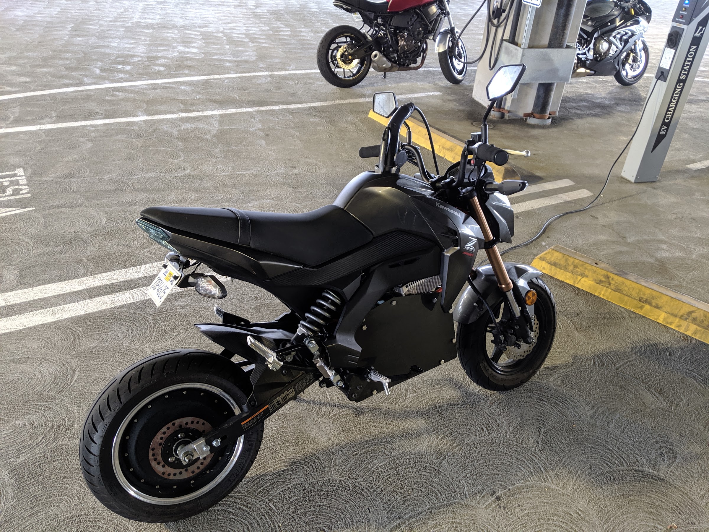
Finally, I reinstalled the tank (now with the charger inside), then reinstalled the fairings. Here's how it looks all buttoned up and plugged into the charger.
Thanks for reading! This has been a fun project and the bike is a hoot to ride.
Here was my totally stock Z125 Pro (excpe the bar end mirrors).
This is a small bike so I decided to go with a hub motor to conserve space. I ended up selecting an 8kW QS hub motor and a Kelly KSL-7275H controller. This system runs on 72V.
Next, I got rid of the engine. Sorry for the pictures in a dark garage. It’s a shared garage for the building and the landlord has the lights come on at night on a timer. That means it is always dark.
Since the hub motor doesn't take up any space the entire engine area is wide open for a decent size battery. Since I’m not a good welder trapped the battery between two plates separated by spacers, with closeouts around the outsides. I modeled it up in CAD to create a file for cutting the plates.
Next step was motor testing. Unfortunately I didn’t take any great pictures of this setup, but maybe that’s for the best so you don’t have to see how messy my bedroom is. I had the wheel/motor on my rear stand and then a rat’s nest of wires between components. This is all temporary and I cleaned everything up before installing on the bike.
I still had a bunch of gas guzzling parts on the Z that needed removal. I took off the grips, fuel system, tank, clutch lever and associated hoses and wires. Now we’re at bare bones. Extra fuel was donated to my Triumph (in the background) which happy drank it up that week.
Next I wrestled the tire over the wheel.
After that, I got everything mocked up on the bike. Overall I like how it looks! The battery fits really well (mounted to the old engine mounts) and doesn't really look all that out of place. The controller is a really tight fit on top. I took some measurements during this mockup install to make some brackets for the controller. I also needed to relocate the horn since that goes right where the controller is sitting.
The wheel/motor will sit slightly behind where the stock one was. I made plug that goes into the back of the swingarm and provides the slotted mount to hold the motor axle. The cable bundle from the motor runs up along the inside of the chain guard toward the controller.
Once I took the battery and ECU out, the DC-DC converter (72V battery step down to 12V to run lights and gauges) and the main contactor fit in there.
I painted the battery box black, then added a strip of black plastic around. This looks a lot better than bare aluminum and the blue battery plus I think the plastic will help protect against small rocks and debris kicked up by the front tire.
Things were getting a little tight with the new components so I also freed up some space by getting rid of the unnecessary wiring. There are a whole lot of wires once I cut the harness open and I really gave those Harbor Freight wire cutters a good workout. I even got a little too snip-happy and cut off the horn (oops). The only thing I really wanted to keep was the lighting circuit. However, it turns out everything runs through the speedometer so once I got rid of that I needed a separate standalone flasher relay. It works now and I reduced the the wiring by a lot.
I figured out some brackets once I had everything mocked up and cut them out of aluminum. I don't have a lot in the way of tools and workshop space so everything takes longer than it should.
The controller packages tightly right above the battery and picks up the old airbox mounts. There is barely any space with steering at full lock, but it does fit.
The DC-DC converter goes under the seat, where the battery used to be.
The bike looks super clean from the right side after installing the wheel/motor. Finally back on the side stand! I also installed the throttle and mirrors.
The wire extensions coming out of the controller are comically oversize since I only bought a few different wire sizes.
Next I trimmed all the wires and connected everything up, both the high voltage and low voltage (lighting) circuit. I also got the speedometer working and calibrated.
For my rear brake, I'm ditching the mechanical brake in favor of regen only. I figure emergency stops pretty much all come from the front tire anyway, especially with a wheelbase this short. The motor controller accepts a 0-5V signal for variable regen so I am getting this signal with a load cell. I mounted the load cell using a custom bracket off the rear brake master cylinder tab and the other end goes to the brake pedal. Since I think a fully rigid brake pedal would feel weird, I used rubber bushings in the mounting holes so there is a tiny bit of compliance like a real brake pedal. The output from the load cell runs through an amplifier to get the 0-5V signal for the motor controller. This turned out fantastic, braking feels really good and just like a firm conventional brake pedal.
I bundled the wiring a little better (still not super neat honestly) and then went for a test ride! Woohoo!
Next I got to work on the onboard (tank mounted) charger. First I cut a hole in the bottom of the tank. There is lots of open space to make sure I have good ventilation.
The charger fits inside (barely) and is fastened with square U-bolts to a bracket spanning the opening. For the picture, everything is in there temporarily since I wanted to add some foam padding where the U-bolts clamp and add trim around the edges to avoid cutting the wires. I cut off the excess U-bolt length after that too.
I like how it looks from the other side. This is a J1772 connector which I have at the charging stations at my work. I was able to fit the stock silver trim ring around the plug housing.
Finally, I reinstalled the tank (now with the charger inside), then reinstalled the fairings. Here's how it looks all buttoned up and plugged into the charger.
Thanks for reading! This has been a fun project and the bike is a hoot to ride.