Hall sensor confusion

ok, that makes sense.
sidenote
I was going to use a led but a led has no real resistance, I hooked 1s2p directly to 3 leds and it was almost like a welding flash. kind of like 20 amps was being pumped into them, they didn't blow and I put a resistor inline so I could use the led normally

that's why I asked about 12v automotive not led, I didn't want to pull 10 amps through the hall sensor
 
goatman said:
I was going to use a led but a led has no real resistance, I hooked 1s2p directly to 3 leds and it was almost like a welding flash. kind of like 20 amps was being pumped into them,

an led (just a bare led, no driver) is a current-operated device, not voltage. it does have a minimum voltage requirement, but actually is operated by current.

so to use one, you need to know what current it was designed to take. then you need to know what voltage you're running it on. then you use ohms law to figure out what resistance it takes at that voltage to get that current, *at maximum*.

you don't want to exceed taht current, because it greatly shortens the led life (if it doesn't blow it up outright), and decreases it's max brigthness, permanently. :(


incandescent bulbs are voltage-operated devices, and self-limit their current draw when used at their rated voltage, to what is needed to operate as designed.

exceed the voltage, and it's just like leds--shortened lifespan. (their max brightness isn't reduced, but they are much easier to burn out at the hgiher voltage from even small vibrations, the moreso the higher the overvoltage).
 
Well, theres the problem, I am a dummy who can't even understand half what AW says. And then I explain it for dummies, but poorly since I am a dummy.

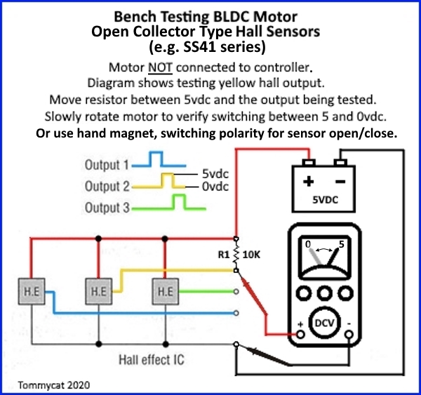
Yes, Dmm goes on the red, and the green or blue or yellow. I thought he meant he put the battery + on the g y or b.

Battery goes on the halls red and black.
 
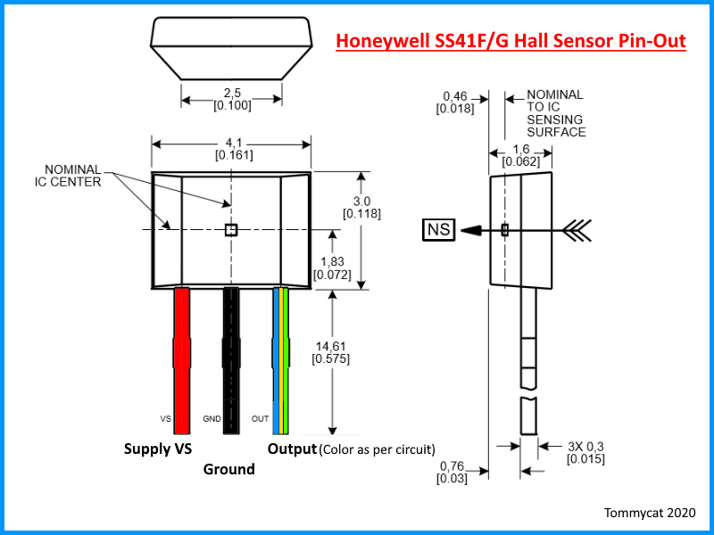
Perhaps a couple of graphics to clarify...


NktFBwJ.jpg


dAAKziF.png
 
I do this exactly, with a 9v battery and 3 12v LED. It worked with all motors that I have tested, so we can presume that all hall sensors can take 9v no problem. Also, I had one of those small Chinese ebike testers, that was powered with a 9v battery as well, although I never checked if it was 9v output on the test wires.
 
many of these motor hall sensors can take up to 24v (some even more) for their +power pin to ground pin. you can look at the spec sheet for the sensor you're testing to know for sure.

there are some that are 5v *only*, and 9v will damage them. but they are not the ones commonly used in ebike motors.

the most common type:

https://sensing.honeywell.com/ss411a-bipolar2

"3.8 Vdc to 30 Vdc supply voltage" though there is a note "For supply voltages above 24 Vdc, a capacitor may be needed between the output and supply pins to ensure proper operation."


fwiw, the actual honeywell-made sensors can operate up to 302F temperatures...who knows what the generic chinese clones can take. ;) might be important for those pushing enough power thru the motors to make them toasty. :p
 

Attachments

  • honeywell-sensing-hall-effect-digital-position-ics-ss400-series-ss500-series-datasheet-3232099...pdf
    1.3 MB · Views: 34
MadRhino said:
I do this exactly, with a 9v battery and 3 12v LED. It worked with all motors that I have tested, so we can presume that all hall sensors can take 9v no problem. Also, I had one of those small Chinese ebike testers, that was powered with a 9v battery as well, although I never checked if it was 9v output on the test wires.

On my little tester box, the Hall connector has 5.0 volts across red/black.
 
I see Honeywell ss41a fine. But I wouldn't mind buying 20 or 30 as I can only find one and I really should replace all three.
Can I get the proper ones for my D.D motors cheap.
I see 3313 and other bipolar don't I want a linear hall sensor ?
Amazon is fine. But I don't want to end up with 30 of the wrong ones. Thank you.
 
I see 3313 and other bipolar don't I want a linear hall sensor ?
Linear hall sensors are used for throttles.
Motor's use bipolar switching, although there is more than one type.
It's always a good idea to see which model you have installed OEM wise if possible. I.E. open it up and look.
 
Honeywell SS 41a from our friend Justin.
What's the difference between bipolar and in and out as in the description ?
Hell I have three motors all by 20 of them for $9 and I'll report back.
As any fool I just wanted the answer yes or no but now with my two left feet I'm going to go forward thank you
 
ALLECIN 20Pcs SH41 SS41F S41 Hall Effect Sensor 41F 0H41 3Pins Bipolar Magnetic Detector https://a.co/d/g8ewZgD
Here's the ones that I'm looking at 20 for $7.99 ?
Hall sensors are cheap, and they're vulnerable. You might as well spring for better ones like Honeywell.
 
What's the difference between bipolar and in and out as in the description ?
SS41F hall sensors are bipolar, so I would think the description fits as they both elude to “digital”. Amazon suppliers descriptions can be sketchy, and also totally wrong… If in doubt, or just to verify, look up the data sheet for the electronic component.

https://www.mouser.com/catalog/spec...4AzdvFHmVN-doPnBgcpbwCTrQ_4hRSVswjv3Tu-HKdBhJ

They are also recommended for use as a common hub motor hall sensor replacement.

That supplier/manufacture may be a bit of a chance also.
I agree with Chalo. It takes a bit of work to replace these sensors… may want to use a higher quality.
But at the very least, “bench test” them before installation.
 
Bipolar means that the sensor switches whenever the field changes polarity in either direction NS or SN. This produces a hall output signal on every magnet.

Unipolar means the sensor only switches when the field changes in the specific direction it's made for (either S-N, or N-S, but not both). This produces a hall output signal on every *pair* of magnets.

Normally the sensors used in motors are Latching type, so that they stay turned on (grounded, 0v output) until the next switching transition is encountered.

Non latching types will turn off as soon as the transition is past, so they will only produce a short pulse. The faster the motor spins, the shorter this pulse is, and the harder it is for the controller to read them (which is why latching sensors are usually used).

Open Collector is normally used, with the pullups inside the controller. Helps to improve signal-to-noise ratio.

Sensors with a normal full-swing on/off output (say, from 0v to 5v, or 0v to whatever vcc is) would only be used with a controller that has no internal pullups (would be something matched to the speciic motor, as anything commonly available willl have internal pullups).

I've made other posts around here with more detail on exactly how various versions of sensors work, and what results you will get with different ones, if you look thru this list:
there are other searches to turn up more info.
 
I soldered the hall sensors then try to glue them in.
I found this to be a mistake.
I'm going to glue them in then solder the wires on. Next time. As I got two glued down.
It was just hard to get the hall centers in the slot with exacto knife screwdriver everything it still seem to have a minor hang up. Maybe old glue . I can't see with my 350 readers ? I'm going to let this dry then go at it from there.
I forgot how difficult this was as I replace these Hall sensors before and shorten the phase wires as they are cut coming out of the axle.
 
Back
Top