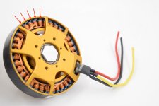
What do you think of these HUGE rc brushless motors?

socalfusions

10 mW
Joined
Feb 17, 2012
Messages
34
I've been searching for the largest Rc brushless motors available and so far these are what I've found. Let me know what you think!

Turnigy 80-100-A 180Kv Brushless Outrunner
http://www.hobbyking.com/UNITEDHOBBIES/store/uh_viewItem.asp?idProduct=5139

This is by far the most common of the larger rc brushless motors I've seen being used in e bike and other related applications. It also appears to be one of the best deals as well.


Turnigy CA120-70 Brushless Outrunner
http://www.hobbyking.com/hobbyking/...y_CA120_70_Brushless_Outrunner_100cc_eq_.html

Here's an even larger Turnigy, although It is almost 5 times the price of the Turnigy 80-100!


Predator 30-8 Brushless Outrunner
http://www.icare-rc.com/plettenberg_predator.html

The Preadtor motor seems to be a bit stronger than the Turnigy ca120-70 while the price, iirc, is about the same.

Hacker A200-8 Brushless Outrunner
http://www.aero-model.com/Hacker-Brushless-A200-8.aspx

This is the most powerful rc brushless motor I've found so far, it seems incredibly powerful for its weight. It is also double the price of the previous two motors.


What do you all think of the performance of these rc brushless motors for ebike/scooter/motorcycle applications? Although I've seen the Turnigy 80-100 in quite a few ebike setups I have rarely seen the last 3 motors in any such setup.
 
socalfusions said:
This is the most powerful rc brushless motor I've found so far, it seems incredibly powerful for its weight. It is also double the price of the previous two motors.

Is this a fair way to compare?

Hacker

Weight 2.585 kg

Kv 110 rpm/V

Kt 0.0868 Nm/A (9.55 / 110)

Rm 0.015 ohms

Km: 0.0868 / SqRt 0.015 = 0.71

Divide by weight: 0.71 / 2.585 = 0.27


Just to head this one off :p
http://www.control.com/thread/1026217558
 
You should type keywords into the search query. This forum has explored and tested these motors to the limits. We've rewound them, added sensors, run them at 100volts, people have made made custom hot rod circuitry to advance the timing. For 7kw +/-3kw these are the motors to experiment with.
 
So far the 5-8 kw motors are drivable with cheep controllers but motors above need more expensive controllers.
 
You should type keywords into the search query. This forum has explored and tested these motors to the limits. We've rewound them, added sensors, run them at 100volts, people have made made custom hot rod circuitry to advance the timing. For 7kw +/-3kw these are the motors to experiment with.
Can you tell me what key words you're talking about? I've searched for: "big, huge, large brushless motor" but didn't get much result.

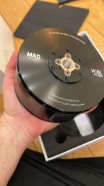
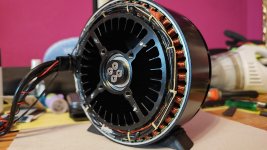
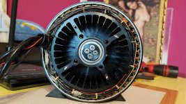
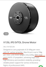
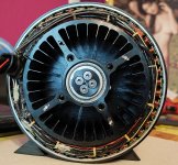
I have a MAD V135L 34kv 24s(100v) 2.2kg motor that I fly my paramotor with (downgraded from the powerfull MAD M50 20kw 4.2kg motor as part of lightening the unit) but, despite an 54inch 137cm recomended prop, it gets hot with an carbon 51inch 130cm prop.

At 5kw for a couple of minutes, the coils get to 100C and in 4minutes 125C at 10-12C ambient and 30kmh airflow. It's rated at 6kw continous (doesn't say the temperature)
The rated temp for magnets is 180C and coil varnish 220C.
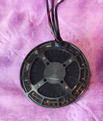
I took the front and rear metal meshes out to improve airflow, not sure how much it helped.
The motor has a centrifugal cooling but I don't think is very efective at those low 1.500-1.800rpm.
If any motor guys here I'd apreciate an opinion on:
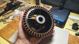
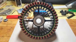
- Why do the coils connections at the back are wraped and not just let uncovered? This makes them bulkier leaving very small surfacs for the air to reach the coils. Some coils are not even seen! And could I unwrap them without risking something?

- would some openings in the front plate help releasing the air? Even if it will interfeare with the centrifugal but since that is already usless.. (The motor is used as a pusher, air flow hits the back of the motor).
So, could I carefully unwrap those back wires and thus make them slimer and would some openings in the front plate improve airflow?
 

Attachments

  • IMG-20240723-WA0002.jpg
    IMG-20240723-WA0002.jpg
    80.8 KB · Views: 8
  • 1000275452.jpg
    1000275452.jpg
    1.3 MB · Views: 6
  • IMG_20250319_191048.jpg
    IMG_20250319_191048.jpg
    2.8 MB · Views: 9
  • IMG_20250322_101922.jpg
    IMG_20250322_101922.jpg
    3.2 MB · Views: 9
  • IMG_20250319_190635.jpg
    IMG_20250319_190635.jpg
    2.8 MB · Views: 10
  • IMG_20250316_171750.jpg
    IMG_20250316_171750.jpg
    2.1 MB · Views: 9
  • IMG_20250316_171716.jpg
    IMG_20250316_171716.jpg
    2.7 MB · Views: 7
Last edited:
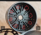
Mill or drill holes in the rotor surface and dremel the edges of the holes at an angle so they "scoop" the air out when rotating.View attachment 368344
Thanks! I too thought of that, making some triangular openings between main reinforcements of the plate , maybe even add some extension blades towards outside to create like an extracting fan. The propeller blades are 5mm in front of the motor front plate so there is space and between blades is unlimited space if I keep the same mounting position.
 
You understand that "180 kV" means 180 RPM per volt, yes?

I use 48V batteries and usually I want an unloaded wheel RPM in the range of 400. So to use a motor with 180 kV, I'd need a roughly 22:1 speed reduction, which would negate any size, weight, and cost advantages of the model airplane motor, while adding a lot of noise, wear and friction losses. If that is what you want, knock yourself out.
The last posts were about a paramotor.
The post above that are from 2012.
Normally you're much sharper Chalo...😉
 
Normally you're much sharper Chalo...😉
I mean to be fair why was this posted in some random 2012 thread that's barely related?

How confident are you the prop pitch isn't too high and the motor is spinning too slowly leading to decreased efficiency? I would look at that first. And then I would make sure the intake airflow path is clear or possibly optimize it with some sort of scoop to direct clean airflow into the motor. Also it looks like a lot of air probably just goes through the middle of the motor where there are no fins so I would block that off so the air is forced through the fin area and the coils more. Also it looks like it has filter screens, if you do make a duct of sorts I would remove the screens from the motor and install screens on the duct instead so they can be much larger and have less resistance. I think drilling holes there is probably a bad idea as you will reduce the performance of that fan, in fact it will probably just start sucking air through the holes instead of through the motor making cooling worse. A duct could also be designed to push air into the coils more effectively.
That's what I do, I resurrect old threads not to make another and another.
-We use E-props carbon props from France. They don't have a pitch number, you show them the motor and they give you a prop. I've asked for the lowest pitch they have..at the base is prety high pitch but the prop is significantly thiner than my 140cm one and the pitch drops rapidly towards the top. I could search for a wood one but it will be havier and less effective.
- The intake airflow is the back of the motor stuffed with cables, wondering why are those cables in sleeves?
- Blocking the middle is something I've thought too but I think those fins in the center need some cooling to as they take heat from the coils. But partialy bloked might be a good idea that I will look into, maybe I will let the screen mesh only on the center.
- The screens were taken out
- Good point about the holes in the front..I'll think about it. Thank you!
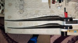
The lower prop is the 130cm I use on this motor, the upper one is the 140cm I use on the bigger M50 motor. Odd thing is the smeller one starts with a pitch slightly larger than the big one..
 

Attachments

  • IMG_20241004_202756.jpg
    IMG_20241004_202756.jpg
    3.6 MB · Views: 4
If the motor manufacturer has a efficiency graph you could use that and the RPM you are typically running at to see where you stand on the efficiency curve, even if heat wasn't an issue I would assume that efficiency of the whole system is key for range and battery size. A slightly smaller prop may let the motor run more efficiently although you have to make sure that gain isn't lost from lower prop efficiency.

Ideally I was thinking about something like a 3D printed insert that fills the center and forces all the air through the fins, the windings, and a little gap around those center spars as they will also act as a heatsink.
 
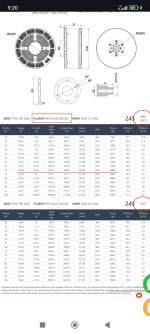
They have two graphs, one for 100C max temp and other for hotter. They used an 54/24 inch prop. I've chose mine to be 51 inch to be lighter on the motor, don't know if mine pitch is near that 24 they used. I don't know how a 24 pitch looks like. But they do state the motor being for large pitch props due to its low rpm 35kv.
But they advertise the motor of being a 20kw motor which is out of the question. Maybe half of that. They do have a note at the botom of the graphs stating that only below 66A is the working zone(I presume they mean continous operation) that's 5.7kw power.
Maybe they meant it to run hot..
 

Attachments

  • IMG_20250406_100612.jpg
    IMG_20250406_100612.jpg
    566.8 KB · Views: 2
  • IMG_20250406_100923.jpg
    IMG_20250406_100923.jpg
    238.9 KB · Views: 2
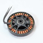
Any idea anyone why these connections between coils are covered in protective sleeves? Other motors have just the naked wires, and take much less space like the other photos (not my motors).
Would the motor work without those wire sleeves and how to take them off? With a hot exacto knife maybe to not need to apply much presure and ruin the wire varnish?
 

Attachments

  • 1000392748.jpg
    1000392748.jpg
    1.8 MB · Views: 4
  • H62b1a71bc72e418d8d2ad7608ca0d9cdo.jpg_720x720q50.jpg
    H62b1a71bc72e418d8d2ad7608ca0d9cdo.jpg_720x720q50.jpg
    49.5 KB · Views: 4
  • Calculate_motor_poles_figure_2.jpg
    Calculate_motor_poles_figure_2.jpg
    316.5 KB · Views: 4
Last edited:
They are there to protect the wires from abrasion caused by vibration. Cheaper motors don't have them because they don't care. You could remove them but you should make sure the wires are secured, possibly by wrapping them with more kevlar/nomex thread like they seem to be now and maybe varnishing them a little so they can't vibrate. Some are also the temperature sensor it looks like. I don't know if removing them would make that much difference but they do cover quite a lot, I guess that's just because the motor has very short stator teeth. They are probably also silicone coated fiberglass sleeving so heating up the knife will be totally irrelevant, using a sharp blade and cutting away from up and away from the wire would be better. Possibly could just cut the cordage and break the adhesive and then move them inboard more and then rewrap them. Not sure if it's the best play as it has some risk of damaging things.

I wonder how much air is actually going through the motor, like if it's actually spinning that fast that fan structure may not really be moving that much air as you said. You could add an additional cooling fan ducted to the motor to force more air through it, although at some point the larger motor would be a better option.
 
Back
Top