• Hello ES! We could use some help to get us past the finish line on building the new knowledgebase for the forum.
    Can you donate? Please see our fundraising page. Thank you!

What ways to best combat voltage sag.

slaphappygamer

🚴‍♂️ Mega poster
Joined
Mar 5, 2022
Messages
838
Location
California
I made a post and it got me thinking. How can you reduce voltage sag? I was reading this article and in the "Lesser Issues and Modifications" and he mentioned that he ran 10AWG wire through the axle (must've been quite a task) to help negate voltage sag. I understand that thicker wire will have less resistance and allow easier current flow. However this is on the phase wiring. I don't know what gauge wire he has on the battery side, but I'm sure it's a non issue here. I'm curious how changing the wire gauge, on the phase wires, can help with voltage sag? I was under the impression that voltage sag happens between the battery and the controller. I know that voltage sag will happen depending on the total circuit resistance, but maybe that also includes the wiring after the controller. My phase wires, on the dual motor build, are pretty long and might be 14AWG. I'm wondering if I should run new phase wiring. Im only pulling 10A each motor, so not very high power. That's also 2 motors, so twice the resistance. Still, same current. I know it's not my battery, I've used two different known good ones. My regular 48v14ah battery usually sags about 4 volts under worst case scenario. This same battery sags about 7 volts with the dual motor build. Might it be just crappy BrainPower controllers that don't respect my 24A, total, current limit? Any input is welcome.
 
I made a post and it got me thinking. How can you reduce voltage sag? I was reading this article and in the "Lesser Issues and Modifications" and he mentioned that he ran 10AWG wire through the axle (must've been quite a task) to help negate voltage sag. I understand that thicker wire will have less resistance and allow easier current flow. However this is on the phase wiring. I don't know what gauge wire he has on the battery side, but I'm sure it's a non issue here. I'm curious how changing the wire gauge, on the phase wires, can help with voltage sag? I was under the impression that voltage sag happens between the battery and the controller. I know that voltage sag will happen depending on the total circuit resistance, but maybe that also includes the wiring after the controller. My phase wires, on the dual motor build, are pretty long and might be 14AWG. I'm wondering if I should run new phase wiring. Im only pulling 10A each motor, so not very high power. That's also 2 motors, so twice the resistance. Still, same current. I know it's not my battery, I've used two different known good ones. My regular 48v14ah battery usually sags about 4 volts under worst case scenario. This same battery sags about 7 volts with the dual motor build. Might it be just crappy BrainPower controllers that don't respect my 24A, total, current limit? Any input is welcome.
I think voltage sag can be calculated with ohms law, using the internal resistance of the battery and the current flowing through it..

I put two of these in series, then parallel them with my 14S pack. Then the IR of combined packs is super low, so less sag.


Discounting the 60C rating by half to be conservative, that's still 150A, combine that with the capability of the pack, and I get almost no sag since I'm pulling a fraction of that current.
 
Phase wire thickness doesn't change battery voltage sag.

If the battery is actually sagging in voltage when measured *at the battery*, it is simply incapable of supplying hte current being demanded. A better battery that is capable of the demand would be required in order to correct that problem. Lower resistance cells,more cells in parallel, better internal interconnects, better wiring inside it, etc.; whatever is needed to make it supply curent with as little voltage sag as possible. (and don't trust the ratings battery and cell sellers provide, because they all lie. ;) ).


But:

if you have voltage drop when measuring across the wires from the battery to the controller in a high-current-test, then decreasing the phase wire resistance would help.

if you have voltage drop when measuring across the wires from the controller to the motor in a high-current-test, then decreasing the phase wire resistance would help.

The best way to find out where a resistive loss is happening is to measure the voltage *on* a wire, from one end of it to the other, or across a pair of contacts, from one side of the connector to the other, or the fuse, holder, etc. This must be done under the worst-case load so you can more easily see the voltage drop (it only exists because of current flwoing thru the resistance). There should be zero voltage across any of those; any voltage that shows up is because of the resistance, so the higher the resistance the worse the voltage drop.
 
Phase wire thickness doesn't change battery voltage sag.

If the battery is actually sagging in voltage when measured *at the battery*, it is simply incapable of supplying hte current being demanded. A better battery that is capable of the demand would be required in order to correct that problem. Lower resistance cells,more cells in parallel, better internal interconnects, better wiring inside it, etc.; whatever is needed to make it supply curent with as little voltage sag as possible. (and don't trust the ratings battery and cell sellers provide, because they all lie. ;) ).


But:

if you have voltage drop when measuring across the wires from the battery to the controller in a high-current-test, then decreasing the phase wire resistance would help.

if you have voltage drop when measuring across the wires from the controller to the motor in a high-current-test, then decreasing the phase wire resistance would help.

The best way to find out where a resistive loss is happening is to measure the voltage *on* a wire, from one end of it to the other, or across a pair of contacts, from one side of the connector to the other, or the fuse, holder, etc. This must be done under the worst-case load so you can more easily see the voltage drop (it only exists because of current flwoing thru the resistance). There should be zero voltage across any of those; any voltage that shows up is because of the resistance, so the higher the resistance the worse the voltage drop.
You could also estimate it if the conductor size is known. Assuming 10 AWG is around 1 milliohm per foot, so if you use 1 ft between the battery and controller, you can calculate the drop for a given current. But if the pack has a 15milliohm IR, that will contribute 15 times as much sag.
 
Ahh. Yes. I’ve seen it calculated with ohms law. For example, my 52v (14S7P) pack has LG MH1 cells. Each cell has IR of .04 Ohms. Multiply by 7 and .28 Ohms. Multiply .28 by current 24A and 6.72v. That’s about the right voltage sag I’m experiencing actually. I'm using the datasheet for IR value.

1758204924669.png

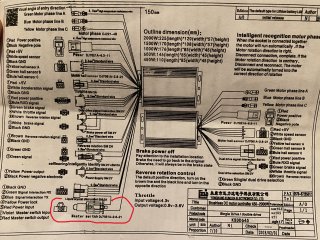
I'm realizing that I'm measuring voltage after the controller. My controller has that plug for an ignition switch. I've circled it in red. Could also be crap controller since when I have the total system current set to 24A, I blow a 30A fuse on my 13S4P 35E battery.

IMG_1260(1).JPG


This is the section of the article I was referring to and why I was wondering if using larger phase wiring would help with voltage sag.

1758202848057.png
 
Last edited:
I think voltage sag can be calculated with ohms law, using the internal resistance of the battery and the current flowing through it..

I put two of these in series, then parallel them with my 14S pack. Then the IR of combined packs is super low, so less sag.


Discounting the 60C rating by half to be conservative, that's still 150A, combine that with the capability of the pack, and I get almost no sag since I'm pulling a fraction of that current.
I have a 14s battery with a 30 amp BMS if l parallel like your doing can I pull 50 amps then ?
 
I put two of these in series, then parallel them with my 14S pack. Then the IR of combined packs is super low, so less sag.

https://hobbyking.com/en_us/turnigy-heavy-duty-5000mah-7s-60c-lipo-pack-w-xt90.html?srsltid=AfmBOopErp0QrulR5axd2bR7mk2qGSYxcgXvtdFUWncz8_C_Or4kzAV5
Discounting the 60C rating by half to be conservative, that's still 150A, combine that with the capability of the pack, and I get almost no sag since I'm pulling a fraction of that current.
What's the spec of your 14S pack? Chemistry? BMS?
 
I made a post and it got me thinking. How can you reduce voltage sag? I was reading this article and in the "Lesser Issues and Modifications" and he mentioned that he ran 10AWG wire through the axle (must've been quite a task) to help negate voltage sag. I understand that thicker wire will have less resistance and allow easier current flow. However this is on the phase wiring. I don't know what gauge wire he has on the battery side, but I'm sure it's a non issue here. I'm curious how changing the wire gauge, on the phase wires, can help with voltage sag? I was under the impression that voltage sag happens between the battery and the controller. I know that voltage sag will happen depending on the total circuit resistance, but maybe that also includes the wiring after the controller. My phase wires, on the dual motor build, are pretty long and might be 14AWG. I'm wondering if I should run new phase wiring. Im only pulling 10A each motor, so not very high power. That's also 2 motors, so twice the resistance. Still, same current. I know it's not my battery, I've used two different known good ones. My regular 48v14ah battery usually sags about 4 volts under worst case scenario. This same battery sags about 7 volts with the dual motor build. Might it be just crappy BrainPower controllers that don't respect my 24A, total, current limit? Any input is welcome.
Minimizing voltage sag first starts at the battery pack side.

Use the lowest resistance cells that you can purchase, use copper interconnects for cell connections, utilize thicker wider interconnects, use a lower resistance BMS and use the thickest battery wires.

After optimizing the battery pack to the bone, you have to think about general system optimizations.

The simplest and best one is to increase battery pack voltage as much as possible. For the same power, a higher voltage system reduces losses considerably; cutting current draw by 2x reduces your losses by 4x. That's why I've been tempted to go with a 72V pack in my next build.

Next in that class is getting a high efficiency controller that minimizes power losses.

After that comes minimizing connector resistance. If you initially plan to go with an XT60 connector, plan using an XT90 connector. XT90 connector? QS8 connector. Contact resistance matters as well so if you can, use high quality gold/silver/nickel plated connectors and if you can design that, avoid disconnecting discharge wires at all.

Finally, use thicker and shorter phase wires if possible. Less inductance and lower resistance is always best.

In summary, if I paid for all of the volts, I'll try to use all of them :)
 
I have a 14s battery with a 30 amp BMS if l parallel like your doing can I pull 50 amps then ?
The cells in my pack are good for 60A, but are saggy 35E cells 14S8P. The BMS is 40A. The most I’ve pulled is 100A+ peak on a launch, but I hit 70A frequently with little sag, which tells me both packs aren’t under much stress. In my application, the piggy back packs aren’t for running high current continuously, but to provide instant acceleration when needed.
 
With my 13S4P 35E pack, I used the cycle analyst to measure pack resistance. It’s at 53.5v and .18 Ohms. .18x25=4.5. A 4.5v voltage drip is what I see on my regular ebike.

I should connect my 52v pack to this bike to measure total pack resistance, instead of going off the datasheet. The 52v pack is about 6 years old.
 
The cells in my pack are good for 60A, but are saggy 35E cells 14S8P.
As far as I am concerned, if a cell is saggy, it's not "good for" whatever it's rating is, only for whatever current that it can handle *before* the sagginess begins. ;)

I'm realizing that I'm measuring voltage after the controller. My controller has that plug for an ignition switch. I've circled it in red.
If you're chasing efficiency / sag issues, you should measure voltage simultaneously at the battery terminals (preferably inside the pack, but outside if that's not possible), and at the controller (at the V+ to the display is fine), with meters that either are "calibrated" to measure identically, or that you have already established and noted the differences in so you can account for those in the measurements.

Doing this tells you how much voltage drop is happening in the wiring / connectors between the two points, so that you can also eliminate this if it's significant (or you just want to get the best performance possible).

The battery-side measurement tells you how bad the battery itself actually is. You can go further with that and measure at all the various series connection points within the pack, to see exactly where the problem is, allowing easier fixing.

But it's almost always the cells themselves, simply not being good enough for the usage to which they are being put. ;)

Could also be crap controller since when I have the total system current set to 24A, I blow a 30A fuse on my 13S4P 35E battery.

A 30A fuse should be able to tolerate 30A indefinitely. Above that, you have to look at the manufacturer's spec sheet for the chart that tells you how long it will take to blow at a specific current. Then you can take how long it takes to blow, and find that current on the chart, and have a good guesstimate of the current your controller is actually drawing (without having to measure it directly, though if you can do that, it's even better).


This is the section of the article I was referring to and why I was wondering if using larger phase wiring would help with voltage sag.
It helps with voltage drop *to the motor* but it doesn't help with voltage sag, which is a battery-side thing.
 
I’m understanding better, that voltage drop and voltage sag are different things. I thought this was the case where there are 2 names for the same thing. I was thinking it be that maybe using 10AWG from the motors to the controllers would help with voltage sag. I have the wire and was thinking of axing the cable near the axle……but I’ll wait on that.

About the 30A fuse. This battery is the same one that I use with my BaseRunner and cycle analyst. I’ve set the BaseRunner to 30A (commuting for multiple days) and never blew the fuse. Since that bike is running with a 25A max, I figured that 12A for each motor controller (24A total) would be safe. But no. These BrainPower controllers don’t want to play nice. I’ve got to get them off the bike before I ride it again. I don’t want to damage a good battery. Especially one that I use daily on my other bike.

Getting a dual motor VESC on this bike would be optimal. Then I can do further trials with more confidence.
 
I was thinking it be that maybe using 10AWG from the motors to the controllers would help with voltage sag. I have the wire and was thinking of axing the cable near the axle……but I’ll wait on that.
Unless you're using really high phase currents, for a high-wattage motor, it probably won't make much difference.

I did such an upgrade on one of my MXUS motors, with solid transformer wire, single-conductor, and I don't remember it making too much difference even with the SFOC5 controller's high-current-capability. If you want to read about that adventure :lol: it's in my SB Cruiser thread from something like 7 or 8 years ago I think, and in Incememed's Hall Sensors Be Gone thread for the beta testing of that controller. Should be lots of pics of it in the SBC thread, and test data.


About the 30A fuse. This battery is the same one that I use with my BaseRunner and cycle analyst. I’ve set the BaseRunner to 30A (commuting for multiple days) and never blew the fuse. Since that bike is running with a 25A max, I figured that 12A for each motor controller (24A total) would be safe. But no. These BrainPower controllers don’t want to play nice. I’ve got to get them off the bike before I ride it again.
They are probably just terrible at current limiting. Bad software, or bad hardware, or both. They might even have the wrong shunts installed. Or they might not have shunts at all, and instead used regular wire in place of them cuz they ran out or whatever. :roll:
 
Wow! Lots of data in that hall sensor b gone thread. I won’t anywhere near the phase current you guys were running. I don’t have a need for any phase amps over 100A.

My 13S4P 35E pack was sagging at about 7 volts. When going up a hill. If the sag was 7v and I know (from the CA) the IR of the pack (.189 Ohms), then these BrainPower controllers were pulling about 37A! No wonder the 30A fuse blew. I'm glad the fuse was in place to do it's job. I've got a new 30A fuse back in there now.
 
FWIW, the CA doesn't acutally "know" the IR. It does math to calculate it from voltage drop vs current. ;) It averages this over some amount of time / readings (I think hte manual has details on that).

(Same with the cell voltage it shows--it just divides the pakc voltage by number of cells you told it in setup....same with a fair number of the readings it conveniently displays).
 
Back
Top