stancecoke
🏍️ Giga poster
Not yet, but I will try to get a M820 also.Do we have any schematics or details of that M820 controller

Not yet, but I will try to get a M820 also.Do we have any schematics or details of that M820 controller
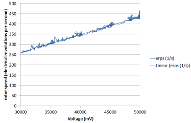
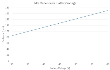


I ran a similar test on the "stand"So I can see no abnormal behavior. Everything is just like in the textbook.

Then I have to adjust the cadence calculation, at 55V the chainwheel speed should be slightly below 160 rpm, according to my measurements. But perhaps you can check the cadence with a simple speedo also.The maximum RPM without load was 181 (55 volts).
I will check it step by step. There are just a few lines of code that are relevant....It seems the problem is with the assist algorithms.
MS.p_human=(uint16_t)((float)(MS.cadence*(torque_cumulated>>MS.TQfilter))*0.00342); //in Watt

MS.i_q_setpoint_temp= MP.TS_coeff*MS.p_human*interpolate_assistfactor()/100;

uint8_t interpolate_assistfactor(void){
    uint16_t interval= speedlimitx100_scaled/5 ;
    uint8_t ui8_speedfactor=0;
    uint8_t ui8_speedcase=0;
    if (MS.Speedx100 < interval)ui8_speedcase=0;
    else if (MS.Speedx100 < 2*interval)ui8_speedcase=1;
    else if (MS.Speedx100 < 3*interval)ui8_speedcase=2;
    else if (MS.Speedx100 < 4*interval)ui8_speedcase=3;
    else ui8_speedcase=4;

    ui8_speedfactor = map(
            MS.Speedx100,
            ui8_speedcase*interval,
            (ui8_speedcase+1)*interval,
            MP.assist_profile[level_to_array_element[MS.assist_level]-1][ui8_speedcase],
            MP.assist_profile[level_to_array_element[MS.assist_level]-1][ui8_speedcase+1]);
    return ui8_speedfactor;
}

int32_t map (int32_t x, int32_t in_min, int32_t in_max, int32_t out_min, int32_t out_max)
{
  // if input is smaller/bigger than expected return the min/max out ranges value
  if (x < in_min)
    return out_min;
  else if (x > in_max)
    return out_max;

  // map the input to the output range.
  // round up if mapping bigger ranges to smaller ranges
  else  if ((in_max - in_min) > (out_max - out_min))
    return (x - in_min) * (out_max - out_min + 1) / (in_max - in_min + 1) + out_min;
  // round down if mapping smaller ranges to bigger ranges
  else
    return (x - in_min) * (out_max - out_min) / (in_max - in_min) + out_min;
}I'm not very familiar with code. Is it normal for the "uint16_t human_power" variable to have no effect?You can fork it and run the algorithm with different values for cadence, speed, etc. I have not found any abnomality so far....
Sorry, I don't get your point. human_power is calculated from cadence and torque.But if you change this parameter to the value "uint16_t human_power," nothing changes.
That's what I thought. It just looks customizable. But changing it doesn't change anythingSorry, I don't get your point. human_power is calculated from cadence and torque.
OK, that's in the same range as @Waynemarlow reported for the original M510 Firmware in #123The power drop issues started at 125 RPM
There's one caveat. I tested my M510 with a no-load throttle test using the stock firmware. The maximum cadence on the display was 155 RPM. That's the value you calculated earlier. Could it be that EBiCS is misreading the cadence?Хорошо, это в том же диапазоне, что и сообщал @@Waynemarlow для оригинальной прошивки M510 в #123.
Yes, as written above already, I have to adjust the calculation. I will fix it tonight and publish a new pre-release.Could it be that EBiCS is misreading the cadence?
Then I have to adjust the cadence calculation, at 55V the chainwheel speed should be slightly below 160 rpm,
The cardiovascular system recovers faster than muscles. Therefore, for most people, a high cadence is more beneficial over long distances.Most EBike riders operate in that 50 -80 rpm cadence where the human body can actually covert torque into rotation. A few like myself like that 80 - 100 rpm from historical reasons of riding analogue bikes where a constant spin rate using very close ratio gears was the most efficient.
Shorter cranks are now the norm but perhaps they were not introduced for higher cadence as you perhaps think. Some years ago a few of us were reporting striking the ground ( pedal strikes ) on pedalling in rough ground with full suspension bikes. To get around this the bottom bracket height was both raised and crank lengths shortened. About the same time 48volt motors ( over volt ing 36volt motors ) were beginning to make an appearance in the likes of the TSDZ2 project. Benefits were felt immediately in that the motors now spun into that sweet rpm most analogue riders were used to and short cranks were now needed.The cardiovascular system recovers faster than muscles. Therefore, for most people, a high cadence is more beneficial over long distances.
In the E-MTB world, there's a recent trend toward short cranks, partly to support a high cadence.
140 RPM is high, especially without clipless pedals. This is one reason to question the accuracy of the display on the EBiCS.
Of course, there are several reasons. You mentioned the main one (catching rocks, etc.). Some people note a more natural stance, others a more comfortable knee angle.but perhaps they were not introduced for higher cadence as you perhaps think
It looks like:You could try to follow the traces from the opamp to the processor with the multimeter. There will be some resistors and/or ferrite balls on the way
OK, thank you for checking. This should be the same as on my controllers. Strange, that @mk00 melted his battery contacts thenOut A - Phase A
Out B - ADC Battery
Out C - Phase C
Out D - Phase B
I've just published V0.006:I will fix it tonight and publish a new pre-release.
 github.com
I did a few short rides:I've just published V0.006:

Release EBiCS_for_M510_BL3+38_V0.006 · EBiCS/BAFANG_GD32F303RCT6
change log: V0.006: add battery indicator based on pack voltage add trip indicator adjust cadence calculation bugfix for power drops bugfix for PWM on at startup increased frequency for cadence fra...
I've added the bin files for both bootloader versions, 3 and 38.
regards
stancecoke
No, the amplification of the human power is already linear increasing with the cadence. I will print some relevant variables to the debug frame tomorrow and report. Perhaps you can try to use the new log function that @mdi just introduced.Could this be due to the missing function described
Can this run on Ubuntu?No, the amplification of the human power is already linear increasing with the cadence. I will print some relevant variables to the debug frame tomorrow and report. Perhaps you can try to use the new log function that @mdi just introduced.
Sure, but the torque has not to be high if the cadence is high. I've tested a lot of algorithms for calculating the motor current setpoint and of course I tried exponential approaches. But I ended in this quite simple logic, as it gives the most natural feeling and sensitive response over the whole cadence range. We will see tomorrow, if something goes wrong in the code.At higher rpms the ability of our legs to produce torque on the pedals gets diminished
github.com