• Hello ES! We could use some help to get us past the finish line on building the new knowledgebase for the forum.
    Can you donate? Please see our fundraising page. Thank you!

BAFANG M215 (BBS01 CAN bus), M315 (BBS02 CAN bus), M510, M560, M820, CR-A101 FOC Open Source EBiCS Firmware for GD32F303 processors

Quetion:
1.what is the difference between Battery current limit and Motor current limit in canable tool v2.2 and what values you suggest for M560?
2.How can it be related to power of the motor?
 
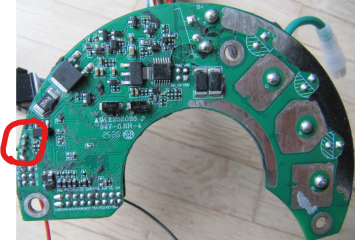
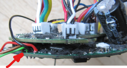
I guess that means full un-potting of the controller is needed, and then removal of the connector pcb to get access?
No, if you have disassembled the controller from the housing, there is enough space to solder in the wires for the debugger.

1784365888949.png

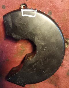
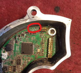
You can try to mill a groove into the aluminium housing to get access to the four pins (+3.3V, GND, SWDIO, SWCLK) from the bottom. But I never tried that.
And of course this not necessary for a standard user at all, as you can flash the firmware non invasive by the BESST/Canable Tool and the display connector ;)

1784366040820.png


1784366509672.png
1784366566389.png
 
Last edited:
Thanks, that was valuable info. Seems doable. By the way, do you have a complete bin-dump available from that board?
The original Bafang firmware I mean
 
what is the difference between Battery current limit and Motor current limit in canable tool v2.2
The motor current defines the torque of the motor and follows the relation
Code:
battery current = motor current * duty cycle

at low speed, you need just a low duty cycle to get a high motor current, as the BEMF of the motor is low. At high speed, the BEMF is high, the duty cycle will be near 1, so battery current and motor current are almost the same.

How can it be related to power of the motor?
That's quite easy. The electrical power is Ubat * Ibat.

The mechanical output power of a BLDC is:

Code:
mechanical power = torque * speed * 2PI 
torque = motor constant * motor current
mechanical power = motor constant * motor current * speed * 2PI

I don't suggest any current settings, we often read about broken clutches, if you set the torque too high ;)
 
Last edited:
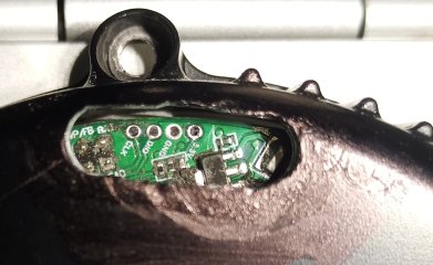
You can try to mill a groove into the aluminium housing to get access to the four pins (+3.3V, GND, SWDIO, SWCLK) from the bottom.
The groove could look like this, even a bit smaller. The hole for the fastening screw gives a good orientation.
The distance from the surface of the housing to the transistor is about 6mm, so you should not mill deeper than 5mm.

IMG_20260718_133412_965~2.jpg
 
Last edited:
Yep, something like that. That kind of hole could quite easily be sealed again afterwards. Thanks!
 
The motor current defines the torque of the motor and follows the relation
Code:
battery current = motor current * duty cycle

at low speed, you need just a low duty cycle to get a high motor current, as the BEMF of the motor is low. At high speed, the BEMF is high, the duty cycle will be near 1, so battery current and motor current are almost the same.


That's quite easy. The electrical power is Ubat * Ibat.

The mechanical output power of a BLDC is:

Code:
mechanical power = torque * speed * 2PI 
torque = motor constant * motor current
mechanical power = motor constant * motor current * speed * 2PI

I don't suggest any current settings, we often read about broken clutches, if you set the torque too high ;)
Thanks it helped a lot. As i can see max motor current is always higher than max battery current (mine is 25A) i think max motor will be about 30-40A to start with. Btw what happens if i set it lower than battery max?
 
Noticed that the only difference between the M215 and the M315 bin files are the first main software (MSW) byte (i.e. 0xA800), what is in that position? M215: 0xC9 and M315: 0x81
Checksum CRC-16-CCITT-FALSE at 0xA810, and the checksum cover position 0xA820 till the end of MSW, correct?
 
Btw what happens if i set it lower than battery max?
The max battery current will never be reached, as the duty cycle can't be bigger than 1.


what is in that position? M215: 0xC9 and M315: 0x81
This is the hardware information for the bootloader. It prevents the bootloader to flash a firmware, that's not suitable for the hardware.
In the bin files for the bootloader the first 32 bytes are a header, not the compiled code itself.
We have identified three different bootloader versions since now, each needs a different start address for the interrupt vector table.
 
Last edited:
To avoid the problem with different start addresses of the vector table, here is a generic solution that adapts to the address location:

1. In gd32f30x_flash.ld, specificly relocate main() to immediately after the vector table
29 .text :
30 {
31 . = ALIGN(4);
32 *(.text.main) /* Place main() directly after isr_vector table */
33 *(.text)
34 *(.text*)


2. In main.c, adjust the first part of main(void)

extern const uint8_t *__gVectors;
uint32_t getPC(void){ return((uint32_t)__builtin_return_address(0)); }

int main(void)
{
uint32_t tmpPC = getPC(); // At what address has the Boot placed the code?
uint32_t vectTableSpace = (uint32_t)&main - (uint32_t)&__gVectors;
uint32_t tmpVectApproxAddr = tmpPC - vectTableSpace;

// We want the offset only: remove Flash start addr, and align with 0x200
uint32_t vectTableOffset = tmpVectApproxAddr & 0x00FFFE00;

nvic_vector_table_set(NVIC_VECTTAB_FLASH, vectTableOffset);
 
The idea was to avoid the need for ifdefs, depending of bootloader variant. Regardless of where in the flash the bootloader stores the software, the application will calculate and set up the interrupt vector table offset correctly. Will have to look at the fork later, currently on a trip.
 
I installed EBICS soft for M560 v008 and it worked very good (I used battery max curr 15A, motor max curr 21A) and was surprised with the power and efficiency. But then I would like to check out ver .0083 and when I by mistake did not switched off power before unplugging canable USB plug, the display turned off and I had to remove battery to restart. But then when i was calibrating sensor by openbafang canable 2.2 prog it behaved strangely: first there was long period of motor buzzing without moving pedals then pedals were moving for a period of time. Then I tried throttle: no movement but motor buzzing and the same with walk mode ( I had tried twice). I tried soft ver. 008 but behaviour was the same. And had to return to M560 1.6 soft that finally was working without any issue. Moreover display looks like on the photo attached - not sure if it is connected to soft installed or not (with bafang soft 1.6 display looks similar but different pattern of distortions). I'd be very thankful for any advice, please. I used besst tool for installation of the software and canable 2.2 for EBICS config.
 

Attachments

  • IMG_20260718_182322497.jpg
    IMG_20260718_182322497.jpg
    376.4 KB · Views: 11
Last edited:
But then when i was calibrating sensor by openbafang canable 2.2 prog it behaved strangely:
If the position sensor calibration fails, the motor can't turn properly. Have you tried to reset to factory settings by clicking on the torque sensor calibration button and then retried the position sensor calibration?
 
I've added the latest beta bin files to the GitHub repo to make it more convenient to find them. Searching this thread for the latest attachment for the interested motor is pretty tedious :)
You can find them in the "latest_beta" folder for the corresponding branch now.
Of course the "official" releases are still in the release area.

M215/315

M510/560

M820
 
I reset to factory settings and it worked so I returned to testing v0083, thanks Stancecoke.
Now ,I am playing with different settings and trying to figure it out.
Do you have any idea what to do with display because it is now almost invisible (I think this is because I had the bike on a rack during torrential rain and this happend after that)
 
@stancecoke
I’ve encountered an interesting issue with the new M510 motor I recently received from China. The revision is still FC 3.0.
The problem is this: when there’s a load on the torque sensor, the motor starts, but the assistance stops almost immediately.
Additional details:
- The torque sensor and cadence sensor show normal values.
- I’ve performed calibration multiple times.
- The throttle works perfectly.
- The walk-assist function works great.
- The assistant works well on the stock firmware.
My minimum goal is to figure out what’s causing the issue: is it the new torque sensor or the controller?
 

Attachments

  • IMG_20260725_182819.jpg
    IMG_20260725_182819.jpg
    1.8 MB · Views: 7
Last edited:
My minimum goal is to figure out what’s causing the issue: is it the new torque sensor or the controller?
I compared this motor with another M510 running on EBiCS. I found that the controllers are completely identical, so I didn’t touch them.
However, there’s a slight difference in the torque sensor’s marking. After replacing the torque sensor, I got a motor that works fully with EBiCS. Let me remind you again that the “non‑working” torque sensor worked perfectly with the stock firmware.
I can also recall another strange thing about this torque sensor. There were 2–3 cases when, after calibration and a few runs in “Walk Mode,” the motor’s calibration got reset. But this didn’t happen again after multiple calibrations.
 

Attachments

  • IMG_20260726_005346.jpg
    IMG_20260726_005346.jpg
    2.9 MB · Views: 10
  • IMG_20260726_005247.jpg
    IMG_20260726_005247.jpg
    1.7 MB · Views: 10
Let me remind you again that the “non‑working” torque sensor worked perfectly
Hm, is cadence shown correctly In the display?
There is no function to calibrate the torque sensor in EBiCS, the button in the Canable tool is used for a factory reset.
 
Last edited:
Hm, is cadence shown correctly In the display?
Unfortunately, I only checked the data in the Canable interface — everything there looks correct. The number of points on the torque sensor shaft remains unchanged. The new shaft works perfectly with the old sensor.
There is no function to calibrate the torque sensor in EBiCS, the button in the Canable tool is used for a factory reset.
I know about that. I used this function once — just to reset things in case there were any errors in my settings.

I still have the “faulty” sensor. I’ll be able to prepare the motor for testing this issue within a week. It will be an M560 motor with an M510 controller. I assume the mechanical part from the M560 won’t interfere with reproducing the problem.
 
The motor current defines the torque of the motor and follows the relation
Code:
battery current = motor current * duty cycle

at low speed, you need just a low duty cycle to get a high motor current, as the BEMF of the motor is low. At high speed, the BEMF is high, the duty cycle will be near 1, so battery current and motor current are almost the same.


That's quite easy. The electrical power is Ubat * Ibat.

The mechanical output power of a BLDC is:

Code:
mechanical power = torque * speed * 2PI 
torque = motor constant * motor current
mechanical power = motor constant * motor current * speed * 2PI

I don't suggest any current settings, we often read about broken clutches, if you set the torque too high ;)
I found my bafang M560 too powerfull, how I can decrease a torque of the motor by program settings (battery current limit, motor current limit or assist levels/torque sensor assist values ?? all of these are related to motor current though) and how evaluate actual torque gained (nominal is 120Nm)?
 
how I can decrease a torque of the motor
Reduce the max motor current. If you want to keep the max torque, but only reach it with more effort from the rider, decrease the multiplier.
You are the first one, who wants less torque. Normally I read "I need more torque! More power! More speed!" ;)
1785323837081.png

1785323763385.png
 
Last edited:
Back
Top