Started My First Electric Conversion Project - Problems with Votol Controller

Jacob84

1 mW
Joined
Aug 26, 2024
Messages
15
Location
Germany
Hey everyone,
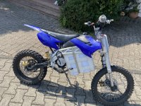
I've recently started my first electric conversion project about a week ago and could use some advice. I’m converting a pitbike with 17/14 inch wheels to electric and here’s what I’ve got so far:
  • Battery: 72V, 40Ah, 60A continuous, 180A max
  • Motor and Controller: 3000W, 80A, 72V Controller
  • Current Gear Ratio: 4.5
I hooked everything up, but I ran into a big issue right away—there’s absolutely no torque. The motor was stuttering even with no load at low rpm, and under load, it wouldn't move at all. I checked all the phase wires and hall effect sensors, and they all seem fine. Thinking it might be a controller issue, I upgraded to a Votol EM50SP (60A continuous, 180A peak, 3960W peak).

After connecting everything with the new controller, I got the bike to move, but it still has very little torque. I even have to push start it. However, it managed to reach 52 km/h on a very slight downhill, which shows some promise.
Does anyone here have an idea what might be causing these issues or what I should check next?

My Specs:
  • Battery: 72V, 40Ah, 60A continuous, 180A max
  • Motor: 3000W, 80A, 72V
  • Controller: Votol EM50SP, 60A continuous, 180A peak, 3960W peak
  • Wheel Size: 17/14 inches
  • Gear Ratio: 4.5
Thanks in advance for any help or suggestions!
 
Are you sure you have the phase and hall sensors hooked up in the right order or have used any learning/auto-tune feature on your controllers? Some incorrect combinations will move the wheel, but not very usefully:

1000003656.jpg

Matching color isn't reliable especially if you bought the components separately.
 
Thank you for the quick response! I haven’t actually tried this yet. I only checked the wires and the functionality of the hall sensors with a multimeter. Could incorrect wiring result in the motor heating up and having low torque?
 
Are you sure you have the phase and hall sensors hooked up in the right order or have used any learning/auto-tune feature on your controllers? Some incorrect combinations will move the wheel, but not very usefully:

View attachment 358770

Matching color isn't reliable especially if you bought the components separately.
Okay, here's happend:

First, I tried using the self-learning cable, but I didn't notice any significant change. Then, I followed the first step you mentioned (changing the phase wires). This definitely helped— the motor stopped rattling and had a smooth start(still with very little torque and speed). I managed to drive for about 200 meters, but I started losing power quickly. When I looked down, I saw smoke coming out of the vent holes, so I probably burned my motor.

Does this give any clues as to what might be going wrong? Technically, the motor should have been able to handle this, right?
 
Do not ride or run the motor with the wrong hall/phase combination. You can fry the motor, controller, or both quickly if you do.
Sounds like you cooked your motor already, but you can test the windings to confirm.

There are a few different procedures for running the self learning routine, depending on you controller. This works for many
 
Last edited:
Do not ride or run the motor with the wrong hall/phase combination. You can fry the motor, controller, or both quickly if you do.
Sounds like you cooked your motor already, but you can test the windings to confirm.
I did test it free spinning first, and when I saw that the motor wasn't stuttering like it used to, I assumed that the wiring was correct. Does this change anything in terms of diagnosing the problem?
 
I did test it free spinning first, and when I saw that the motor wasn't stuttering like it used to, I assumed that the wiring was correct. Does this change anything in terms of diagnosing the problem?
There’s only 1 of 36 combinations that is correct and current draw with the wheel elevated should be very low.

In addition to testing the windings, test the hall sensors as well. If the motor phase wires are shorted, you’ll need to check your controller next.
 
There’s only 1 of 36 combinations that is correct and current draw with the wheel elevated should be very low.

In addition to testing the windings, test the hall sensors as well. If the motor phase wires are shorted, you’ll need to check your controller next.
Is there an easy way to check the current draw? I just spun up the motor to see if it still works, and it sounded fine. I also saw a few videos about the 72V 3000W kit I got, and they all seem to have way more torque. I'm just very confused that it also didn't work with the old controller and motor combination. I guess I will switch back to the old one and try a few different combinations of phase wires. Also, if the motor is damaged, should I get a kit like this again, or something else? The kit costs 180€.
 
Is there an easy way to check the current draw? I just spun up the motor to see if it still works, and it sounded fine. I also saw a few videos about the 72V 3000W kit I got, and they all seem to have way more torque. I'm just very confused that it also didn't work with the old controller and motor combination. I guess I will switch back to the old one and try a few different combinations of phase wires. Also, if the motor is damaged, should I get a kit like this again, or something else? The kit costs 180€.
Testing and troubleshooting are part of DIY e-bikes. If you don’t have the patience to do either the right way, then perhaps a factory built option would be better for you. There are a lot of options and prices have been coming down a lot.
 
Testing and troubleshooting are part of DIY e-bikes. If you don’t have the patience to do either the right way, then perhaps a factory built option would be better for you. There are a lot of options and prices have been coming down a lot.
I'm pretty new to electronics, so I'm feeling a bit clueless here. I followed the steps in the image I found and managed to find one wiring layout that seems very promising. The motor appears to be fine—I've checked the voltage coming from the hall sensors, and the motor spins very quietly now. When I tried lightly slowing down the wheel with my hand, it felt way stronger than before. The only issue is that it’s spinning in the wrong direction.

I didn't want to push it too hard before checking the current draw, but overall, things look much better, and I’m happy to keep testing and troubleshooting. This whole process has been a learning experience for me, and I didn’t expect it to be this tricky. I really appreciate all the help from everyone here!

For reference, I also tried switching the yellow and blue hall sensor wires, as well as the yellow and green phase wires, but that made the motor stutter again.
 
Here are some pictures for reference.
 

Attachments

  • 5B71D3EA-A255-46E2-B52F-73E486E92E8D.JPG
    5B71D3EA-A255-46E2-B52F-73E486E92E8D.JPG
    1.2 MB · Views: 14
  • IMG_9270.jpeg
    IMG_9270.jpeg
    2.5 MB · Views: 14
  • IMG_9271.jpeg
    IMG_9271.jpeg
    2.3 MB · Views: 15
Thanks for all the help! I got a Votol cable on the way. After switching the phase wires (to controller colers not wire colors) and the hall sensor wires, I got the motor spinning the right way.

I checked for noise and heat, and everything looked good. I took it for a quick test ride, and the motor stayed very cold. I kept testing step by step, going a bit faster each time. I also connected the learning wires (which I probably should have done right after changing the phase wires), and that made things even smoother. After letting the wheel spin at low to medium RPM with the learning wires connected, it seemed to dial in perfectly.

On my last run, I got up to around 60-70 km/h (haven't measured it yet), and there was still way more speed to go. The motor and controller were just slightly warm afterward, so that was a relief.

But it struggled a bit going uphill—it actually shut off for a second, then kicked back in and kept going. I think I need to tweak the software settings and maybe gear it more for torque. I'd rather have a lower top speed, around 60 km/h, instead of hitting 90 km/h.
Just confirming that you used the correct software and procedure when running the self-learning function, similar to below.

 
I think I need to tweak the software settings and maybe gear it more for torque. I'd rather have a lower top speed, around 60 km/h, instead of hitting 90 km/h.
About the only option is gearing down, smaller counter-shaft sprocket, bigger rear sprocket.
Or lower voltage.
Current Gear Ratio: 4.5
That's a pretty fast ratio.
 
That's a pretty fast ratio.
Yes, I calculated that it’s about 77 mph, and I’m currently looking into gearing options.

The main problem right now is that it can’t get up even the slightest hill. It just cuts off power after 10–20 meters. I just got the cable, hooked it up to my Raspberry Pi, and checked everything, but it looks fine. The current draw is almost zero with the wheel free-spinning at half throttle. I might need to simulate some load. The current max is set to 50A right now. Maybe it will exceed 50A or give me an overcurrent warning, but I’m not sure how safe that is.

I also thought I might have a faulty battery, but the voltage drop under load is less than 2V.

I will be checking the current draw under load, but maybe it’s just the absurd gear ratio I have right now.
 
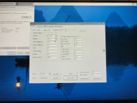
Here are all the Pages of the Software while connected (I think the software always says em-100)
 

Attachments

  • IMG_9291.jpeg
    IMG_9291.jpeg
    2.9 MB · Views: 6
  • IMG_9290.jpeg
    IMG_9290.jpeg
    1.8 MB · Views: 5
  • IMG_9289.jpeg
    IMG_9289.jpeg
    2.6 MB · Views: 5
  • IMG_9288.jpeg
    IMG_9288.jpeg
    3.5 MB · Views: 10
  • IMG_9287.jpeg
    IMG_9287.jpeg
    4 MB · Views: 6
I will be checking the current draw under load, but maybe it’s just the absurd gear ratio I have right now.
I just found out that the cause of the power cutting out is fault code 00000040 or 0x40. I found this document: Controller Fault Code PDF, and it says:

MOTOR_BLOCK 0x40 lock motor failure - Motor stalled, check for overload.

This would make sense because I'm in a very low RPM range when it happens, but when it happend, it was only at 14A.
 
I've been doing some more testing, but I still haven't figured out why the motor stalls under the lightest load. Yesterday, I opened up the motor to find out how many pole pairs it has. It has 6 magnets, so I'm assuming that means it has 3 pole pairs. In the software, it was originally set to 24, so I changed it to 3. This might have made a difference, but I'm not sure.

I tested it again and got the fault code 00000040 again at 25A. I have absolutely no idea why this is happening. I'm no longer thinking it has something to do with the gear ratio because when the motor runs, it can go up even a steep hill for about 10-20 meters, but then it cuts out without warning. It also stutters at a specific RPM, and nothing gets even slightly hot.

Does anyone have any idea what's causing the cutouts or the stuttering at a specific RPM?
 
3 pairs is strange. That's tiny. Is it an RC motor? The picture looks weird too:
IMG_9271~2.jpeg
It's definitely not any of the common ebike mid drives like CYC or BBSHD.

I don't think a drone motor can drive a bike, but there is a successful RC build thread for one on the forum. I don't think even that has any real pulling power, a bike being much heavier than a drone. The torque rating is just insufficient.

If you do want to use a drone motor, I think you have to lookup the RPM range it is designed for, then add a couple extra gears between the motor and the wheel so the motor is running at its preferred RPM for your voltage as per its KV rating. A typical geared ebike hub motor has gearing so the motor can spin 5X faster than the wheel, for example, since electric motors work better at higher RPM. Even then, I think drone motors are just too small in general.
 
It looks like a pit bike motor to me like this one:


In which case it does indeed have 3 pole pairs. The motor has very low torque and operates at very high rpm, so it relies upon low gearing. That’s why it has a tiny front sprocket and the trick is to use a timing chain instead of a regular bike chain, otherwise it would cause problems with the front sprocke.

These motors are used on Razor kids dirt bikes with tiny back wheels.

The Razor MX350 dirt bike is a popular choice to modify, because it’s relatively cheap and easy to get an adult level of performance out of a kids toy.

The OP has a 4.5:1 gear ratio which should be ok on a small wheel, but maybe the 14” rear wheel is causing the problem.


IMG_0237.jpeg
 
Last edited:
Here is a top of the range Razor that has been modified. It still has a small back wheel and a large rear sprocket.

IMG_0238.jpeg
 
It looks like a pit bike motor to me like this one:
Exactly. I would have modified a razor, but we don't get them in Germany, so I got a used 17/14 Pit Bike and Yes the gear Ratio is very bad right now, but it can easily get up a fairly steep hill but then cuts out, but it also cuts out under less load, so I don't think it's the current draw. The Setup right now is power wise good but would be perfect with a better gear ratio.

Right now I don't know what causes those cut-outs, it only says:
MOTOR_BLOCK 0x40 lock motor failure - Motor stalled, check for overload.

If anyone has any idea what could cause this problem, it would be amazing, because power wise It's just like I imagined.

Thank you.
 
Here are some pictures of the current form, the battery will go up another 20cm if I make a proper case for it. Since, it's currently encased in 3cm thick foam.
 

Attachments

  • IMG_9292.jpeg
    IMG_9292.jpeg
    5.1 MB · Views: 6
  • IMG_9293.jpeg
    IMG_9293.jpeg
    5.2 MB · Views: 7
  • IMG_9294.jpeg
    IMG_9294.jpeg
    4.5 MB · Views: 6
  • IMG_9295.jpeg
    IMG_9295.jpeg
    5 MB · Views: 7
You may get a better response if you create a new thread stating that you have a Votol controller.

I don’t know very much about them, so I can’t help, but I do understand what you are trying to accomplish with this build, using these components.
 
Back
Top