Ezee "Sprint" bike
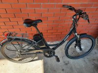
I'm trying to fix a friends bike, it's probably close to 10 years old. It's pretty much stock, but has had the battery replaced. 36V front hub motor, pedal assist.
The bike developed an intermittent fault while riding, powering off using "ignition" key and power back on would usually resolve the issue. Until one day it completely stopped. Powering on the ignition key turns on the Battery indication, the rear light and a red LED on what I think is the controller. The PAS level indication on handlebar display does not come on, and adjusting using arrows makes no difference (this part used to work for PAS level selection). Local bike shop reckoned the led "display" on the handlebar needed to be replaced but this was not done (about $90). I'm not convinced as it looks more like a controller or broken wiring issue to me.
The only thing I've tried so far is connect a different 36V battery to see if that changed anything, and it did not.
It's been sitting in my basement and I'm a bit apprehensive about where to start given the formidable wiring harness on this bike. I'm used to "simple" throttle only ebikes that run sensorless controllers, without display. I don't know where to start with this one. Has anyone had the same issue with this bike or can point me in the right direction?
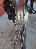
Alternatively, can anyone suggest a basic replacement controller that would work with this EZEE motor? I might try run it at 48V. I've read that others had issues with these motors running backwards with aftermarket controllers. I've only worked with DD motors so not 100% sure what's needed for this one (speed sensor wire is needed I think). Throttle only would be fine.

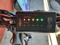
No PAS indication on display:
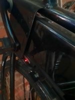
Red Light near downtube on controller:


I'm trying to fix a friends bike, it's probably close to 10 years old. It's pretty much stock, but has had the battery replaced. 36V front hub motor, pedal assist.
The bike developed an intermittent fault while riding, powering off using "ignition" key and power back on would usually resolve the issue. Until one day it completely stopped. Powering on the ignition key turns on the Battery indication, the rear light and a red LED on what I think is the controller. The PAS level indication on handlebar display does not come on, and adjusting using arrows makes no difference (this part used to work for PAS level selection). Local bike shop reckoned the led "display" on the handlebar needed to be replaced but this was not done (about $90). I'm not convinced as it looks more like a controller or broken wiring issue to me.
The only thing I've tried so far is connect a different 36V battery to see if that changed anything, and it did not.
It's been sitting in my basement and I'm a bit apprehensive about where to start given the formidable wiring harness on this bike. I'm used to "simple" throttle only ebikes that run sensorless controllers, without display. I don't know where to start with this one. Has anyone had the same issue with this bike or can point me in the right direction?
Alternatively, can anyone suggest a basic replacement controller that would work with this EZEE motor? I might try run it at 48V. I've read that others had issues with these motors running backwards with aftermarket controllers. I've only worked with DD motors so not 100% sure what's needed for this one (speed sensor wire is needed I think). Throttle only would be fine.

No PAS indication on display:

Red Light near downtube on controller:


