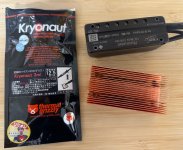
Phaserunner - How would you use this existing copper heatsink?

Joined
Oct 19, 2014
Messages
95
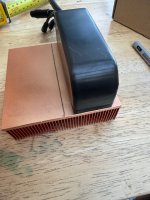
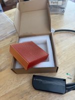
Hi all, thought I might just put this out there in case someone has made something similar. I’ve had this chunk of copper sitting around for years and have finally got my health and free time to line up to get a few things done I hope!

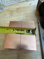
My plan is to simply cut this large heatsink down the middle, along the line you can see in the photo, and use one half for each of my two phase runners (different bikes). I’m thinking just drill four holes to line up with the tapped M4 holes in the phaserunner and use some CPU thermal paste between the surfaces, relying on the screws for clamping force. The phaserunner is exactly the same length as the heatsink, but an edge of approx 8mm remains on each side if I divide the block in two, and I am thinking of using this to attach some type of bracket which I can easily screw or zip tie to the bike.

Early on I used the PR without a heat sink and found it lasted only 1-2 minutes under load drawing 40A. I then rigged up a small aluminium heatsink with zip ties and thermal paste which I’ve used ever since, this significantly delays thermal rollback and really does what I need 90% of the time, but I’m hoping this thing will take care of that final 10% of hill climbs especially with the cargo bike (200kg bike, 72v8ah molicel pack, 12T Mac in 24in rim).

Any suggestions, experience, ideas welcome! I know this isn’t really a complex project, probably doesn’t need over working, but damn some of you lot are clever, and maybe I’m missing some obvious and cool idea here 😉
 

Attachments

  • IMG_9673.jpeg
    IMG_9673.jpeg
    126.3 KB · Views: 19
  • IMG_9670.jpeg
    IMG_9670.jpeg
    111.4 KB · Views: 18
  • IMG_9671.jpeg
    IMG_9671.jpeg
    132.7 KB · Views: 17
  • IMG_9672.jpeg
    IMG_9672.jpeg
    123.8 KB · Views: 18
Any suggestions, experience, ideas welcome! I know this isn’t really a complex project, probably doesn’t need over working, but damn some of you lot are clever, and maybe I’m missing some obvious and cool idea here 😉
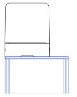
One might wish to consider lining up the surfaces on one side so that the 5 mm through holes could be used to mount the Phaserunner to the bike ... (just a thought).
Phaserunner ASSY End View.jpg
 
Seems like that would be great, for 2 reasons.

1) copper transfers heat better than aluminum.

2) I’m guessing the proposed copper heat sink is larger than the existing aluminum one. That will also dissipate heat better.

Do you have photos of how the PR are currently mounted?
 
I use the same setup. I made a template of the PR base to drill holes to mount the PR from the bottom. Then use zip ties to mount it all with the fins inline forward
 
Grin now sells a custom aluminium heat sink set for the Phaserunner. It's thin with many blades, which are surfaces to couple to the air to maximise heat dissipation. It probably works well.
Appreciate the mention.. I checked their website a couple of months ago, and even sent a query looking for one. No dice. Now I have a reason to ding my plastic again. Thank you.

 
I solved my overheating PR issues by heat-sinking it to my Aluminium frame with thick thermal padding. Now I can run 60A+ all day long without issue. :)

Cheers
I'm genuinely happy for you.

I have 1800 ft. elevation gain in 12 miles (on a trike)- that's my return trip home... so i'm usually loaded with necessities. I also have no aluminum frame to effectively absorb heat. Summer temps here frequently average into the 90's, and it's not unusual to see cookers well into triple digits like we had the summer of 2023. I also have a lot-on-my-plate right now, so the funds spent to have a bolt-on solution works peachy for me.
 
That block does not couple to the air very well
That copper block has an insanely larger surface area than the bottom of the phaserunner and will dissipate heat into the air a magnitude of order better than without, especially exposed on a moving bike. The block doesn't just add more thermal mass, which you seem to be implying, but adds significantly better dissipation.

---

@Bush mechanic -- If you have a good printer, Grin supplies the phaserunner dimensional diagram to help you map out the places to drill.
 
Thanks everyone, good points here.
Do you have photos of how the PR are currently mounted?
I'm sorry to say that I do...but it does in fact do a passable job most of the time!
Screenshot 2024-10-05 at 9.50.38 PM.png
consider lining up the surfaces on one side so that the 5 mm through holes could be used to mount the Phaserunner
I think this might be the quick easy way to do it for now - bolt PR to copper, use zip ties to hold it on there for immediate use, then follow up with brackets once I find something the right size
I would consider that the Phaserunner may be able to supply heat faster than the copper block can dissipate that heat to the air
Definitely, if pushed hard, but our ambient temperatures are pretty low and with reasonable air flow I'm hoping it will be an improvement over the current one.
I solved my overheating PR issues by heat-sinking it to my Aluminium frame with thick thermal padding
That is a clever idea - when you say thermal padding do you just mean a thick layer of paste?
If you have a good printer, Grin supplies the phaserunner dimensional diagram to help you map out the places to drill.
Good idea, will use this for sure, thank you!

I recall an interesting discussion on Stack exchange (I think, can't find it now unfortunately) regarding factors when comparing copper and aluminium heat sinks. Notable points were that 1) if you have poor airflow then differences in performance between the two quickly diminish once the copper has soaked up all it can hold, and 2) poor thermal coupling between load and heatsink similarly negates the advantages of copper.

The shape of the PR is a bit frustrating with regards to thermal coupling, with the 1mm x 10mm channel that runs the length of the unit reducing the direct contact area quite a lot, but I might cut a narrow strip of 1mm sheet to slide in there with thermal paste.
 
Last edited:
A thermal pad is like double sided tape and kind of spongy. They come in many sizes and thicknesses. Most pads can be stacked to increase thickness. Here is an example. A thermal pad would be nice because as the heat sink is compressed against the frame, the thermal padding will (depending on thickness) conform around the top each fin giving more metallic contact to the pad.
 
Very nice. I wasn't actually aware they were effective enough for significant heat transfer, but had a quick read up and seems like a lot of people are successfully using them for CPUs and similar. I'll keep it in mind.
 
Yeah, thermal pads are a bit more forgiving for uneven or bumpy surfaces and can be reused a limited number of times. Thermal paste is better for heat transfer, but messy and difficult to apply in my situation.
They also make thermal double sided tape which I've used before. Works well. :)

Cheers
 
In the picture in post #13 the Phaserunner already has a heatsink. Is that on the side that you intend to mount to the new copper heatsink? So the copper heatsink will replace the aluminum heatsink? I would make rough estimates of the exposed surface area of the existing heatsink, and of the new heatsink, to make sure it actually will be a significant gain. The copper fins seem less tall than the aluminum fins, but there's a lot more of them.

Regarding heat transfer etc: it's true that copper is about two to three times as good a heat conductor as aluminum (400W/m*K vs 100 - 200 W/m*K, depending on the aluminum alloy and temper), and thermal paste and oxide and paint layers are a lot worse (but also a lot thinner), but the limiting factor will be the transfer to air, which is the same for all surface materials, about 5 W/(m^2*K) for still air, and two to ten times as much for moving air. So what counts in the end is the surface area, and the air speed. If your problem is mostly at slow speed, a fan might be easier to add than the copper heat sink, especially if the copper heatsink is not much larger in area.
 
I would make rough estimates of the exposed surface area of the existing heatsink, and of the new heatsink, to make sure it actually will be a significant gain.
It's a bad photo, the length remains the same (100mm), but the new copper one is actually both taller and has more fins: Approx. 30mm vs 20mm tall, 20x fins vs 5x fins. In terms of surface area that comes to about 200cm^2 for Aluminium, vs 1200cm^2 for the new copper one (hopefully I have calculated that right, exposed surface = length x height x number of fins x 2, the multiplier being the two sides of each fin?).

I will probably mount the new assembly further inboard, more centrally under the cargo deck where it will get a bit more airflow, but the fan is a good idea to keep in reserve.

With the significantly larger surface area I suspect the relatively small contact patch between the PR and heatsink might become the bottleneck, even with closely fitted surfaces and good thermal compound.
Well, if you're not allergic to numbers (and from your area calculation it seems you're not), you can estimate the thermal resistance contribution (in Kelvin per Watt) of the different components. I say estimate because getting a good number on the thickness of the thermal compound layer might be difficult.
But assuming say 0.1mm layer thickness of a compound with 2W/m*K (you can get better, Dow-Corning TC-5022 or now TC-5622 does have 4 W/m*K, but a lot of the heat sink compound sellers just seem to make up numbers; I'd be wary of claims like 6 or 9 W/m*K), and assuming (totally made up) 2 by 4 inches contact area, so 5 by 10cm, for 500W (also made up) gives a Delta T of 500*0.0001/(2*0.05*0.1)=5K, so that's not negligible but not so bad.
In comparison, the aluminum heat sink is very limited in the amount of heat it can transfer to air, even at a few m/s speed with a heat transfer coefficient of say 25 W/m^2*K: allowing a Delta T of 50K, you get 50K*25W/(m^2*K)*0.02m^2=25W. Even the copper heatsink can only do 150W under those conditions.
 
Last edited:
It seems weird to put the tiny tips of the cooling fins up against the metal frame. Wouldn't you want as big of a contact area as possible against the metal frame to conduct heat into it?
 
Sounds like a solid plan! Cutting the copper heatsink in half and using thermal paste for better conductivity is the right move. Since you’ve already got an aluminum heatsink working 90% of the time, this copper one should definitely help with that extra bit.

One thing to consider is the airflow. Maybe you can add some fins or even a small fan to improve cooling efficiency. Are you thinking about additional mounting options? That edge you mentioned could be a great spot to attach brackets or secure it with zip ties for stability.

Also, double-check clearances on the bikes to make sure everything fits snugly without any vibration issues. Good luck, and let us know how it goes!
 
I deleted my posts because I realized I am wrong.

I didn't look at the original picture for long enough and thought you were proposing to use a solid block of copper. In fact, you are proposing to use a finned piece of copper.

My dumb.
 
But assuming say 0.1mm layer thickness of a compound with 2W/m*K (you can get better, Dow-Corning TC-5022 or now TC-5622 does have 4 W/m*K, but a lot of the heat sink compound sellers just seem to make up numbers; I'd be wary of claims like 6 or 9 W/m*K)
Thanks for the detailed reply, I’m going use some Kryonaught stuff I bought a few years ago and never used, hopefully it doesn’t go off . Still seems to spread easily enough…no doubt they test under their own lab conditions to achieve the claimed 12.5W/mk.
IMG_9684.jpeg
FWIW I just took a ride with the original heat sink still in place but with improved airflow, relocating PR forwards away from saddle bags, with a small but noticeable improvement before rollback occurred. Hopefully I can have the copper one on there tomorrow for comparison.
 
It seems weird to put the tiny tips of the cooling fins up against the metal frame. Wouldn't you want as big of a contact area as possible against the metal frame to conduct heat into it?
In my case the mounting of the fins against the frame as seen in the photo was purely convenience* and not intended to transfer hear in the manner described by Cowardlyduck, where he is using the frame to dissipate heat. No doubt the way I’ve had it mounted has lowered its effectiveness further by reducing airflow.

*Laziness
 
Maybe you should consider buying or copying Grin's design:
cp-extsinkkit_singleinstalled3_1.jpg

They are pretty clearly more concerned with a solid chunk of metal being up against the metal tubing of the frame and consider the cooling fins a side issue.

I use one of their mounts like that without the fins on my Baserunner and have never had it overheat.
 
Back
Top