C Cab Hot Rod Power Advice

The StreetRunner post-paint redo is currently in the rewiring stage. I will post photos when there is something worth seeing.

I have suffered a mechanical setback...:mad:, but it is fixable. Stay tuned for developments.

In the meantime, I have this for you to ponder.

The Humpty Dumpty Trailer is .. Done, pre-tested, and dump certified. (y):)

Pretest before load testing

I reloaded the brush shown in the video and made a dump trip.

I had a camera in hand at the dump but had to pay more attention to the unloading process (moving the trailer forward, etc.) to take any video. Maybe next trip.

Load testing
 
Last edited:
Hi folks.

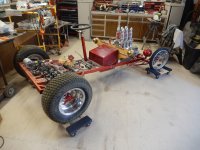
I'm just checking in to see what's what. The StreetRunner is progressing quite quickly. The frame and front suspension are painted and lubed tight, the brake lines/system is in, sans brake bleeding and the rewiring is nearly to a point where it can be tucked away until the body goes on. And the bodywork, my friends, has re-started in just the last couple of days. Current work involves finishing metal fab on the front 'dashboard' area, general detailing like the body seams welds/filler work, and then on to paint.

Other work includes mounting the engine sound system, (which sounds awesome), and buying new plexiglass for the windshield. Finally comes the upholstery, probably a button tuft, as it is within my abilities to make and look somewhat correct.

Oh, and there is a need/desire to replace the motor that went belly up. I'm thinking of upgrading to a 3000-watt motor this time. The electrical system is now all toggle switches and it's set to operate one primary motor, (M1) @3000 watts, (M2) @1800 watts, or both if needed. Not sure about the feasibility of running these two similar motors at the same time. They each will have controllers that are required for their respective voltages/watts/

I have given myself a rather robust timeline to finish it - April 1st. And we all know what day that is - right?
If not done by April Fool's Day, then next year sometime is quite doable.

Am I excited to finally see the end in sight?..👏😃
Look for a couple of photos soon.
 
Am I excited to finally see the end in sight?..
I keep having to dodge that oncoming train that I thought was the light at the end of the tunnel. ;)
 
I keep having to dodge that oncoming train that I thought was the light at the end of the tunnel. ;)
If the train stays on track I hope to be out of the way when it arrives. Phoenix is next door, so if you find you are coming my way, stop by for a chat and see (and hear) the StreetRunner live.
 
No, REALLY! :unsure:, I do know where they all go. I have modified the electrical system by separating the 12 volts from the 48 volts. Most of the amp draw on the 48-volt battery will be needed for the motors, so there is little left for anything else, such as lights and sound system, which will be needed for parade use. So with a new battery, numerous fuses later, most are done, checked, and waiting to be tidied up and secured once the body goes on.
 

Attachments

  • DSCN5681.JPG
    DSCN5681.JPG
    3.3 MB · Views: 5
  • DSCN5682.JPG
    DSCN5682.JPG
    3.4 MB · Views: 5
Final major 'planned' body modification. The dashboard.

It's slow going. Weather permitting (too hot, too cold, too windy), or I'm just too weary. I get in about 2-4 hours a day, which may be a lot for some, but for me, I yearn for the energy I used to have.

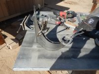
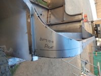
Today though another milestone. Near completion of the all-important final metal addition to the body. All curved pieces were cut and curved by hand. I used a section of a round basketball goalpost to make most of the bends. Using increments of 1" and 1/2" markings as my guide. The front housing is where the switches and gauges go. Tomorrow I will finish cutting and welding the top strips. The goal is to have very little body filler.

Using 1/2" x 1/2" sort-of, as spacers and weld points.
DSCN5684.JPG

Some minor curvature shaping needed
DSCN5690.JPG

Tomorrow I also plan on cutting and welding on the front face plate.
DSCN5688.JPGDSCN5686.JPG
 
Last edited:
Change of plan

As you can see, the plan to enclose the top of the curved pieces didn't happen. Completing the reforming of the dashboard seemed like the thing that needed to satisfy my desire for today.

Before
DSCN5692.JPG

After
DSCN5699.JPG

The plan is to use real oak wood for the top of the dash.
From left to right

Top row -

12-volt gauge,
48-volt gauge,
USB port,
12-volt port.

Bottom row

70 amp circuit breaker with red on/off warning light above it

M1 = Motor One, (2000/3000 watt primary power)
M2 + Motor Two, (1800 watt additional power)
'L' = Head/Running lights
'H' = Hazard Lights
'T' = Turn signals
Hole for the horn button (Used to be for the ignition key, which has been done away with)

DSCN5697.JPG
 
Each day we get closer and closer to the brass ring...so to speak.

Today's progress. The usual details are yet to be completed, but the light burns brighter.

DSCN5700.JPGDSCN5701.JPG
 
Go, Ed, Go. Hope the weather stays nice for you.
What goes in the two big holes in the dash?

Nice to hear from your fetchter. I still recall how much help you have given me.
No self-respecting hot rod would be without ...drink holders...right?
 
Santa visited and left some goodies,
and ate all his cookies.

With a loud, Ho, Ho, Ho, he left in his bright red sleigh,
now it is time for me to play with [my] big red..' sleigh'.

Down it has come, from its lofty perch,
with crafty thoughts for a human's perch.

Time is ticking away,
for a body that has yet a place to lay.

A body we must fit,
lest we know not how we will sit.

The body of work yet to come, belies any notion,
this project will soon provide forward motion.

Yet we persevere, not looking to the rear.
but forward, to the end peeking in the distance near.

Until I return later, enjoy these
images of my current labor.
DSCN5702.JPGDSCN5703.JPG
DSCN5704.JPG

Showing off my $5 swap meet bling, with my touch of anodized red.

DSCN5705.JPG
 
Last edited:
Santa visited and left some goodies,
and ate all his cookies.

With a loud, Ho, Ho, Ho, he left in his bright red sleigh,
now it is time for me to play with my big red..' sleigh'.

Down it has come, from its lofty perch,
with crafty thoughts for a human's perch.

Time is ticking away,
for a body that has yet a place to lay.

A body we must fit,
lest we know not how we will sit.

The body of work yet to come, belies any notion,
this project will soon provide forward motion.

Yet we persevere, not looking to the rear.
but forward, to the end peeking in the distance near.

Until I return later, enjoy these
images of my current labor.
I see a poem. Ed can you sing? How about making a YouTube video with you singing?
 
Morning Marty

Nope, can't sing, nor dance either for that matter.

The poetry comes on a whim now and then.

The pinstriping is an easy matter. I am not a professional painter so others may have other methods.
This method has worked for me.

Think of striping tape as masking tape.

Step one - prep to the primer stage
Step two - apply the strip paint color over your primer coat where you want the stripping to show.
Step three - Choose a strip width and procure (local purchase or online). Vinyl type may be a better choice than crepe paper)
- Color doesn't matter because you will be painting over it anyway. (a contrasting color is better to see while applying)
- However, I will sometimes use the same color that I will be painting the stripe
to give me an idea of what the painted striping will look like.

This is what I've been using ( in the 1/8th size )

Step four - apply striping tape.
Step five - Apply your top color ( or base coat for the final color coat).
Step six - Let the top coat dry, then remove the striping tape. I remove early sometimes.
Step seven - I lightly buff/ sand the top coat, and the striped area to remove any high spots left on the strip edges.
Step eight - Apply a clear coat as desired.

Final step - Step back and admire your work.
 
Last edited:
Much of my time is spent in mental minutia.
That is, dreaming, determining, designing, deciding, with the least amount of time devoted to actual fabrication.

I've been pondering numerous seating configurations and upholstery. I've come full circle back to my two kitchen chairs.
Today I uncovered the chairs and cut the frame apart. It needed tweaking to get it square.

Today's progress

The seat frame slides into the front brackets and is held in place via an attaching point in the rear of the uprights.
It was designed to enable easy removal, providing access to the components underneath.
The next step will be to square up the uprights and weld on plywood attaching points.
Also, there will be additional seat support at the rear curved part of the seats.

A storage box is planned for the area behind the seats.

DSCN5707.JPGDSCN5708.JPG
 
No pics today but things went well until noonish, then the winds came.

I did get the bottom and back seat supports welded on. One seat frame squared and plywood brackets welded on.

Tomorrow more of the same and seat attaching tabs cut, drilled, bent and welded on.
 
Thanks for the lesson. I was a sign painter / pinstripper in one of my past life's. Was working on scaffolding painting a big sign. I fell and died. That was the end of that life.

Watch this.
Roundhand Lettering Demo by Glen Weisgerber
That was beautiful. Very therapeutic, watching the 'paint flowing' on to the canvas.
 
The second seat has been squared and braces welded on.
I still need to add support tabs at the base of the seat back and weld on attachment tabs mid-way up the back.
Seat bottoms come from kitchen chairs minus padding.

A power question for anyone who wants to join in the fun.
With (one) 1800-watt motor no longer usable, I am considering upgrading to (two) 48-volt 3000-watt motors and controllers. It did run on one 1800-watt motor for the backyard test run. How long that would last is yet to be determined.

Or replace the nonworking motor with a 3000 watt/controller and call it a day.
Result running with one 1800 and one 3000 motor????


DSCN5711.JPGDSCN5712.JPG
 
Last edited:
What happened to the original motor?

Running different motors together will likely result in one motor doing most of the work and could give you tendency to steer to one side. You could run 3000w motors with 1800w controllers and it would be no problem. If your original controllers are OK, at least you could save a little money not needing new controllers.
Morning fechter

Thanks for the advice.

What happened to the original motor?
I'm not really sure, but during one of the test runs, the chain came off the right motor. This happened while making a left turn.
I finished the test with just the left motor.
Now, the motor shaft will only turn about a quarter turn before binding. (Bent shaft? Not noticeable)
Battery power won't budge it. You may recall that the drive axles are split.

If my theory and calc's are right.

A test using the bad motor controller on the good motor was good.

Looking forward, the theory is to run primarily on the 3000-watt motor and add the 1800-watt for assist/backup if needed.
A concern is the bat pack is rated at 40 amp and a 3000-watt motor alone is around around 62.5. As a comparison 2000-watt motor would be around 41.6 and the 1800-watt is rated at 33 amps.

If I don't need a matching controller, that would be a plus. But so far I haven't found a motor (3000-watt) by itself. It's probably out there but I'm just not finding it yet.

I looked into adding additional battery power but found it should not be done with the type of battery I have. (Nissan Leaf modules and BMS system) Battery space is already dedicated with virtually no option for changing size or location...unless it's of a smaller size. Also, I separated the 12v and 48v systems, thus reducing the amp draw (though negligible it may be) on the main battery. The 12-volt accessories now have their own LifePO4 18-ah power.
 
Bummer on the motor. Since it's dead, it wouldn't risk anything by taking it apart. You may find something fixable. Maybe not.
SWAG would be a magnet came loose from the rotor. These can sometimes be glued back on with the right epoxy.
 
A concern is the bat pack is rated at 40 amp and a 3000-watt motor alone is around around 62.5. As a comparison 2000-watt motor would be around 41.6 and the 1800-watt is rated at 33 amps.


I looked into adding additional battery power but found it should not be done with the type of battery I have. (Nissan Leaf modules and BMS system)
I dont understand why your Leaf battery modules are limited to 40 amps ?
maybe you have a limit from the BMS, but the modules are capable of much more current than 40 amps. (500+ amps has been demonstrated. !)
 
Last edited:
Bummer on the motor. Since it's dead, it wouldn't risk anything by taking it apart. You may find something fixable. Maybe not.
SWAG would be a magnet came loose from the rotor. These can sometimes be glued back on with the right epoxy.

That's a good idea. I will deconstruct that bad boy and see what's at the 'heart' of the problem. Pics of progress will follow. Thanks for the idea.
I dont understand why your Leaf battery modules are limited to 40 amps ?
maybe you have a limit from the BMS, but the modules are capable of much more current than 40 amps. (500+ amps has been demonstrated. !)

Thanks for joining in Hillhater. It has been a long while since we swapped messages, so here is a reminder of the battery I'm using. I got it from TechDirectclub.com. I believe this module (7 cells) is a Gen 2.
That 55.6-volt reading is only a few minutes old. The battery is +/- 4 years old and recharged only once about 2-3 years ago.
DSCN5713.JPGDSCN5714.JPG
 
Last edited:
Back
Top