
- I have two bike builds with the 36v 250w TSDZ2 - one of the TSDZ2 units is whisper quiet and the other annoyingly noisy
- Now, I've done all of the usual bearing checks, greasing and so on without any improvement, so out of desparation I swapped the bare motor units between bikes and it is the bare motor unit that is noisy, definetly
- So I stripped the noisy bare motor down - no signs of surfaces rubbing nor overheating (hardly suprising given my gentle riding style).
- The rotor bearings seemed fine when rotated by hand so I'm left with wondering my this bare motor is noisier than the other one - any clues folks?
- The only thing I haven't done is separated the rotor from the motor casing cover for visual inspection and maybe replacing the bearings in case one is noise under load - can anyone advise on how to remove the rotor and bearing from the case cover?
- And can Hall Sensors 'play up' in that they don't give a clean 'switch' (as in some sort of switch bounce akin to mechanical switches)?
- And why would one BLDC motor be so different from the other, especially given their very simple construction?

You are using an out of date browser. It may not display this or other websites correctly.
You should upgrade or use an alternative browser.
You should upgrade or use an alternative browser.
TSDZ2 Bare Motor Strip-down
- Thread starter bikes4two
- Start date
Good shout @ilu - both motors are back in their respective bikes at the moment and I'm out riding tomorrow but as soon as I can find half hour or so to tinker, I'll swap over the top connector plate/hall sensor module and post the result.
Mind you, if it proves to be that the hall sensors need replacing, I've no idea where I'd get some from as they look to be a specific moulding for the TSDZ2 - maybe I'm wrong though.
Mind you, if it proves to be that the hall sensors need replacing, I've no idea where I'd get some from as they look to be a specific moulding for the TSDZ2 - maybe I'm wrong though.
Last edited:
Hi @ilu,
- So I swapped over the hall sensors between the bare motor bodies and the noisy motor stayed being the noisy motor, but at least I've eleminated the halls sensors as the cause of the problem.
- The noisy bare motor is back on the bench and during strip-down I saw how to separate the motor casing head from the rotor - it just pulls off - lol
- Next job is to remove the three bearings shown in Fig 5 in post #1 and there is another bearing on the rear of the rotor
- I'll keep this post updated as I move along and put some pics in that others might find useful.
Yes, bought both TSDZ2 from pswpower within a few weeks of each other. Both have OSF on them.
I swapped the bare motor units between bikes and seeing as the noise moved over with the motor, there's no logical reason that I can think of to swap over the controllers, can you?
Further, the external cables to the controller are very well sealed in so I'd be reluctant to disturb them.
I've now stripped the rotor down and am about to measure up the bearings for replacement even though in the hand they seem OK.
I noticed there was a shim washer between the single bearing and rotor which I need to check that it is doing what it should.
The shim washer is similar to the brass ones associated with the blue gear fitting (which for some reason on this motor was absent, but now replaced).
Pics and other info coming soon - thanks for your input @calab .
- In answer to my own question, the rotor spindle can be removed from the motor casing by first removing the black connector block which exposes the spindle end, then a light tap with a suitable drift will spearate the spindle from the casing.
- Using a drift might not even be necessary - a sharp tug by hand might be enough.
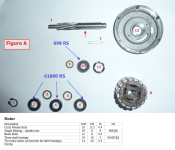
- On the spindle end is a wave washer, then a 698 RS bearing followed by a 0.5mm brass shim washer that sits between the bearing and magnet assembly.

I've ordered up replacement bearings (4 in number) but in the meantime I've knocked up a diagram and documented (in draft) some info which others might find useful.
When I've re-assembled everything with the new bearings, I'll update this post as to whether the noisy motor is no more - fingers crossed!
Motor Casing screws – pozi head, M3 x 48mm (replaced with new screws as the original screw heads were damaged during disassemble as were very tightly fitted and head material is on the soft side).)
When I've re-assembled everything with the new bearings, I'll update this post as to whether the noisy motor is no more - fingers crossed!
-------------------------------------
Rotor
| Description | O/D | I/D | W | No |
| Wave Washer | 18 | 12.5 | 0.4 | |
| Single Bearing – spindle/case | 19 | 8 | 6 | 698 RS |
| Brass Shim | 12 | 8 | 0.5 | |
| Three shaft bearings | 19 | 10 | 5 | 61800 RS |
| Two brass shims (sit between the three bearings) | 14 | 10 | 0.1 | |
Motor Casing screws – pozi head, M3 x 48mm (replaced with new screws as the original screw heads were damaged during disassemble as were very tightly fitted and head material is on the soft side).)
Rotor Assembly
- On rotor spindle 1 place bearings 2, 4 and 6 with shims 3 & 5 between bearings 2/4 and 4/6 respectively.
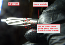
- The bearings and shims need to be pushed down onto the spindle splines far enough to allow the reinsertion of the circlip 7 into the spindle indent shown by the arrow. Figure B is a close-up of the spindle showing where the first bearing 2 engages with the splines.
- Insert key 7 into the keyway on spindle 1 and then push the rotor magnet assembly 8 onto the spindle 1, then shim 9 and bearing 10.
- Place wave washer 11 into the bearing cup in the bare motor case top 12.
- Place the spindle assembly into case top 12 which will likely require some light tapping with a mallet to get bearing 10 seated adequately.
Attachments
Last edited:
Woop woop woop! Replacing those 4 bearings has done the trick - bare motor re-assembled and fitted back into the TSDZ2 body and the motor now runs as quiet as the one on my other bike.
Of the three old 61800 RS bearings, one of them didn't feel quite as smooth as the other two by the meerest amount but maybe at high RPM it was responsible for the noise. However for around 15 USD I just changed all 4 - result!
Of the three old 61800 RS bearings, one of them didn't feel quite as smooth as the other two by the meerest amount but maybe at high RPM it was responsible for the noise. However for around 15 USD I just changed all 4 - result!
@bikes4two
Thank you for this excellent description and your perseverance in solving this problem without replacing the complete bare motor.
Thank you for this excellent description and your perseverance in solving this problem without replacing the complete bare motor.
seattlesockey
10 mW
Anyone replace the brass shims and wave washer? Where did you find them?
I wish I knew where we could get these too.Anyone replace the brass shims and wave washer? Where did you find them?
asterduc
1 mW
- Joined
- Mar 26, 2018
- Messages
- 18
Great post, thanks. I'm facing the same problem, swapped motors between 2 bikes and the noise moved with the motor. Will order bearings and do repair next week. Thank you for the good detailed explanation, appreciated.I've ordered up replacement bearings (4 in number) but in the meantime I've knocked up a diagram and documented (in draft) some info which others might find useful.
When I've re-assembled everything with the new bearings, I'll update this post as to whether the noisy motor is no more - fingers crossed!
-------------------------------------Rotor
Description Wave Washer Single Bearing – spindle/case Brass Shim Three shaft bearings Two brass shims (sit between the three bearings)
Motor Casing screws – pozi head, M3 x 48mm (replaced with new screws as the original screw heads were damaged during disassemble as were very tightly fitted and head material is on the soft side).)
Rotor Assembly
Edit: on re-assembling the stator/rotor, the two are held together by six M3 screws with Pozi heads. The heads are soft and were showing signs of damage from several unscrewings, so we're replace by new M3 x 50mm screws, four of which had to be reduced to 48mm.
- On rotor spindle 1 place bearings 2, 4 and 6 with shims 3 & 5 between bearings 2/4 and 4/6 respectively.
- The bearings and shims need to be pushed down onto the spindle splines far enough to allow the reinsertion of the circlip 7 into the spindle indent shown by the arrow. Figure B is a close-up of the spindle showing where the first bearing 2 engages with the splines.
- Insert key 7 into the keyway on spindle 1 and then push the rotor magnet assembly 8 onto the spindle 1, then shim 9 and bearing 10.
- Place wave washer 11 into the bearing cup in the bare motor case top 12.
- Place the spindle assembly into case top 12 which will likely require some light tapping with a mallet to get bearing 10 seated adequately.
asterduc
1 mW
- Joined
- Mar 26, 2018
- Messages
- 18
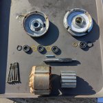
Just another picture of a disassembled motor. This one has received water during high pressure cleaning and as a result it was complete rusty inside. Just like 'bikes4two' I found one 61800 bearing not feeling right, so will replace all bearings and hope that 'll solve the noise problem.
Attachments

Similar threads
- Replies
- 12
- Views
- 1,730

- Replies
- 5
- Views
- 1,218
- Replies
- 0
- Views
- 765