You are using an out of date browser. It may not display this or other websites correctly.
You should upgrade or use an alternative browser.
You should upgrade or use an alternative browser.
Bafang BBS01 CAN throttle not working
- Thread starter Jakuda87
- Start date
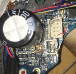
Is on the picture, in the orange circle, is there damage too? Be careful there because that big capacitor can be charged with battery voltage! The thing is maybe the controller can be repaired but you need to follow the traces from component to component until you reach the source of the 5V. It can't be done from a distance via the pictures.
If you can't do it then the solution is to find someone who can or buy a new controller. Where did you bought this one?

If you can't do it then the solution is to find someone who can or buy a new controller. Where did you bought this one?

Can you post a picture under good light from that additional board where the blue wire arrives? And is there a marking for the blue wire, which letters if any? It keeps puzzling me because on some other Bafang canbus controllers the additional board is for lights output.
Not between the 2! Measure between ground and left pin. That short middle pin no need to measure. Then measure between ground and pin on the right. Make sure display is on. left pin should be input voltage, right pin should be (normally) 5V out.
To be clear as possible, position left and right orientation just like on your picture..
To be clear as possible, position left and right orientation just like on your picture..
Last edited:
Do you have any voltage between ground and left pin? Which is input pin. If your right pin is ground like you said then it's probably shorted. Remove battery and measure in continuity mode between ground and Right pin. If zero Ohms it's probably shorted. If it's possible desolder it and afterwards measure on the pcb in continuity mode between ground and that right solderpad. If still zero ohm then you still have a short between there and the TPP pin.
Added; if it's to difficult to desolder, heat up the left pin and lift it 1mm and do the same for right pin. Then you can measure as mentioned above without removing the component...
Added; if it's to difficult to desolder, heat up the left pin and lift it 1mm and do the same for right pin. Then you can measure as mentioned above without removing the component...
Last edited:
How do you mean the hard way? Destroyed it ?? If that 78M05 is completely removed then there should be no short on right solderpad but you say it still is so you have to follow the trace from that right solderpad and test the components along the trace for shorts.
It looks like it's better that you give the controller to your friend if he has some knowledge regarding electronics. Maybe he is able to repair it for you. About BBS01 canbus controllers i did find one on a webshop with the same connectors as yours.
TommyCat
10 kW
Why doesn't the BLUE harness wire terminate at the 8-pin connector across from Meter Port...?
In the picture from post 65 if 20190928 is controller fabrication date then it's old. And i'm beginning to think this is a "special" version who knows. With the usual BBS01 UART there are a few (under another name) where the throttle wire is used for lights! output or maybe as input to switch light on who knows.
I have in the past read some posts about those special UART versions made for Aldi and perhaps for Lidl too in Europe. But the display had usually a 6 pin connector instead of 5. There was some activity around it in German forums.
In one instance in a Dutch forum i remember a post where someone tried to add a throttle at such "special version" i believe also using the blue wire and at full throttle instead of motor spinning his front light came on.
It's my believe an "additional board" in a BBSxx has something to do with the lights, maybe that's the reason for jakuda87 his throttle did not work because his blue throttle signal wire connects to that additional board.
Also the following confuses me even more, quote post 57 "This harness has also light wires- black goes to ground, and red to pin marked BREAK (on the other side of controller)" end quote.
So on that 8 pin PCB connector the pin with marking "BREAK" has a white wire but it ends up via his harness cable as a red wire for the lights according to the quote. So is het break signal line or voltage for lights...
The cable out of his controller is 8 pin male, and you can plug in a 1T4 harness cable like the ones used for the BBSXX Canbus motors from Varstrom or the ones from PSWPOWER.
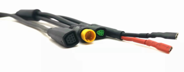
But if a cable (seems for M500 and M600) from the picture below (with lights connection at the front) fits too on a BBSXX Canbus then at which pins on the BBSXX canbus pcb connects it... If it can be plugged in, i expect that will give unexpected results on a normal BBSXX Can motor compared to a 1T4 cable... So i wonder if the controller from Jakuda87 is a normal version or a special version once made for some big client because also his power connector seems to have some extra small pins, maybe for batt. communication or so.
PS I have no BBS01B canbus, nor a M500 or those cables and it's the first time i see the internals from a BBS01B canbus controller thanks to the pictures from Jakuda87. If someone else has pictures from the BBS01B canbus internals, please post them so we can compare the pcb connections.

TommyCat
10 kW
In one instance in a Dutch forum i remember a post where someone tried to add a throttle at such "special version" i believe also using the blue wire and at full throttle instead of motor spinning his front light came on.
All good information!
+1If someone else has pictures from the BBS01B canbus internals, please post them so we can compare the pcb connections.
I looked at wiring diagram for the above cable and that positive wire from front light ends up at the PCB on the pin marked "brake".
And that is what Jakuda87 also measured on his BBS01 canbus controller.
if using a 1T4 cable then it is the brake signal line that ends up on the PCB pin marked "brake".
And that is what Jakuda87 also measured on his BBS01 canbus controller.
if using a 1T4 cable then it is the brake signal line that ends up on the PCB pin marked "brake".
btw.
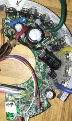
this is how my previous UART controller looks like


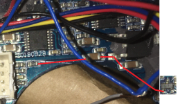
btw. do you know what elements should be where arrows point out? I chipped them off when removing isolating goo.
It was also flooded, and I replaced a few mosfets- after all it was working partially (it started only when turned chainring backwards a bit)
this is how my previous UART controller looks like


btw. do you know what elements should be where arrows point out? I chipped them off when removing isolating goo.
It was also flooded, and I replaced a few mosfets- after all it was working partially (it started only when turned chainring backwards a bit)
Similar threads
- Replies
- 23
- Views
- 1,055
- Replies
- 5
- Views
- 1,010


