
I bought these packs off EBay with the intention of removing the batteries, but now I am wondering if I might hook them in series to create a 65V 8.7AH battery pack in the configuration shown in the picture. Does anyone know where I can find connectors that would work for that purpose?
10 pin Battery Connectors for Vyaire Battery Packs
- Thread starter tothehilt
- Start date


The connectors you might find in devices with similar functions, like old laptops, etc. I don't know what the manufacturer or model of the specific connector you need is, but it may be molded into the connectors (inside the battery packs) you have there, if you want to look for a part number you can buy from Mouser, Digikey, Farnell, etc.
They look like low-power/low-current device batteries (like medical devices, laptops, etc), so the BMS in them (if typical) is unlikely to survive anything like an ebike/etc usage. The cells are probably also low-capability; at a guess they are 3s3p. The FETs or other similar control circuit (if there is one) in the BMS is unlikely to be able to deal with breaking a circuit that includes more than one or two of them in series (the full voltage of the whole series stack will end up across the FETs when they turn off to protect the pack).
So in that event, to use them for anything beyond their designed output, or to series them, you'd need to bypass the BMSs in them and use an external one wired to each cell group in each pack, if you want automated protection, and don't want to keep having to monitor the cells manually during charge and discharge.
The BMS might be designed only to signal the device to stop drawing power and to turn off, and so it might not actually have any shutoff protection circuitry other than a fuse. (which will probably be fairly low current). In this event, you'd still want to use an external BMS so you can get automated protection, or monitor manually, unless you can reverse engineer the datastream from the built-in BMS to decode the data it outputs and have your system respond as the original device would have. In this event it is also possible the BMS has to be told to turn on by the device. Sometimes it isn't a data communication, but just a signal line that goes high or low, and that's a lot easier to figure out.
Thanks, that was very helpful, even though much of it I did not understand. I’m an electrical neophyte, but did manage to build a pressure contact battery pack by following the examples on this site. I will post it up sometime. Trying to hook these battery packs up in series looks like it may be more trouble than it is worth, and it sounds as if it may not even work. I am not opposed to manual monitoring, that is what I do with the pressure pack, but with this I wouldn’t be able to detect individual cells that are going out of balance.
eMark
100 kW
The connectors on those 6 packs look to be 10s (11 contact points). Is it possibly a jst-hx connector ...
Have you checked the voltage variance of the parallel groups recording voltages and variance between the ten p-groups on each of the 6 packs? This will give you a better idea of the condition of those 6 battery packs. You may have to open them up and salvage the best cells.
With DMM probes go down the line readin DC voltage of each parallel group as done with this 5s jst-hx female connector.
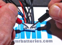
Even startng at the wrong end reading reverse (minus) polarity will still read correct voltage. Can't short a parallel group
proceeding down the line one parallel group at a time. Total voltage reading with each probe on 1st and 11th contact.
Have you checked the voltage variance of the parallel groups recording voltages and variance between the ten p-groups on each of the 6 packs? This will give you a better idea of the condition of those 6 battery packs. You may have to open them up and salvage the best cells.
With DMM probes go down the line readin DC voltage of each parallel group as done with this 5s jst-hx female connector.
Even startng at the wrong end reading reverse (minus) polarity will still read correct voltage. Can't short a parallel group
proceeding down the line one parallel group at a time. Total voltage reading with each probe on 1st and 11th contact.
Last edited:
If they're unused, they may have never been charged/maintained, either, in which case the internal BMS could have drained the cells dead in the time (years?) they've sat unused.
If you read zero volts at all contact combinations, thats the most likely possibility.
If your'e not sure you're making contact from probes to the battery contacts, you could try a flat (bladelike) type of contact rather than a wire, since that is what they're designed for.
Or just open one of the cases up and check them directly. They';re probably ultrasonically welded together at the seam, and it is dangerous to poke around in there by cutting open with a knife or prying them apart (easy to damage a connection or a cell). If you are careful, you can clamp a hacksaw blade to the edge of a table, counter, etc, so that it only has just enough of it's teeth exposed to cut thru most (but not all) of the casing thickness, probably a millimeter or maybe two, you can then rub the casing's seam along the teeth until you have cut almost all the way thru all the way around the battery case. Then reset the blade one more millimeter exposed, and very slowly repeat the process, checking at each rub on the blade to see if it has cut all the way thru yet. When it has cut thru anywhere, it may be possible to just pull the halves apart with your hands at that point.
Most of the time they use some form of doublesided tape to secure the cells in the casing, but somtimes they glue them. Both usually respond to gentle heat by loosening somewhat, if you have troulbe getting the halves apart.
OK, found some time to mess with these batteries again. There is something about the connectors I do not understand. I only get continuity between the first four connectors from the left, negative side and the first four connectors on the right side, but I cannot jump the gap between the two connectors in the middle to test the voltage. I have some battery packs with the same connector from another company, same situation. These packs are used, so I tore open one, not an easy task (thanks AW for the advice, will incorporate it when I get serious about tearing them all up) but I managed to test one battery and it came in at 1.2 V. Ugh! I charged it on a variable power supply to 3.5V and will see how it holds its charge.
I don't understand what you mean about the continuity and the gap.
Continuity means (for this) direct connection (short circuit) between two points in a circuit (essentially zero ohms between connector contacts).
Something to remember about continuity or resistance testing is you can't do it directly on a circuit that has power applied and voltage difference across two points you're measuring--the current flow changes the reading you would get, and can actually damage your meter.
Measuring voltage from every contact to every contact, showing identical voltages at some, *may* indicate direct connection between those that are the same voltage, but doesn't necessarily.
If by "gap" you mean some contacts that don't measure anything to other contacts, that could mean they aren't internally connected, or have circuitry blocking your measurements, etc. You'd have to physically trace out the circuits and connnections and draw it all out to determine what is actually connected to cells, vs circuits, and what those circuits are and do.
If by "one battery" you mean a single cell, 1.2v is too low to safely recharge. Anything under 2v means the cell may be damaged in a way that could lead to bad things (including potentially fire) later on during recharging or discharging (or even just sitting there charged), and this could happen at any time in the future, with no warning.
If by "one battery" you mean a whole pack, 1.2v for what is probably 3 cells in series, and a least 2 in parallel, is very very dead cells, even less reusable than a single cell at that voltage (but I wouldn't re-use either one).
If you do decide to ignore the potential fire hazard and recharge them anyway, make sure you use a variable-current charging supply that lets you use a very tiny trickle current (a few mA at most) to bring them up to at least 2V+, and then increase that slightly until it's at least 3V, at which point you could charge at whatever the spec sheet for those cells says you can charge at. (you would have to look up the spec sheet from the cell manufacturer based on the markings on the cells. If they don't have markings, I would assume a few hundred mA maximum charge rate, say 200-300mA or less, as a safe limit).
If you use a non-current-limited power supply to charge with, then the damage to the cells from that is compounded with the damage of overdischarge, and increases fire risk.
Last edited:
Thanks for your prompt and detailed replies.
“If by "gap" you mean some contacts that don't measure anything to other contacts, that could mean they aren't internally connected, or have circuitry blocking your measurements, etc.”
Yes, that is what I mean. Except that I don’t get a reading between any contacts, but I’d do get continuity, as measured by the beep signal on the multimeter, between contacts 1-4, and contacts 7-10, nothing between 5-6 - “the gap.”
I charged the battery to 3.41V last night, it is now at 3.37.
Similar threads
- Replies
- 83
- Views
- 6,664
- Replies
- 14
- Views
- 248
- Replies
- 0
- Views
- 319
