rkosiorek
100 kW
I was looking for a load to connect my Battery packs to for testing. I was thinking of using some big power resistors but the price for those was prohibitive. Next I though of some heating elements made from resistance wire. Same problem. Next I thought of a big bank of 100W bulbs. Not bad but I live in a bachelor apartment. If my testing goes past my bedtime I won’t get any sleep with the lights on all of the time.
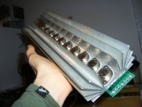
While cleaning out a drawer I found a bunch of really BIG HEATSINKS from old P4 CPU’s. and a 50A 50mV shunt for a panel meter. I got the idea for an active load.
I was thinking of something capable of 500W, 50A or 100V whichever came first. I also have a few IRFB4110 FETs.
So I sketched up a basic idea. Using the 4 or 5 of the FETs in parallel on those heatsinks switching the current through that shunt resistor. Add a opamp or two in a feedback loop with a pot to control it and I might even be able to make the whole thing adjustable.
So I sketched up the idea. And here it is:

The reason I have it here is so that I can get some input from the real engineers in the group. i have a few questions. Am I on the right track? Will the opamps be able to drive the FETs?
The idea is this. The FETs are driven by a comparator. One input of the comparator is tied to a pot used as a resistive divider. The output of the pot will be 0V to 0.5V. the FETs are in series with the 50A 50mV shunt resistor. The voltage across the shunt will go to a X10 prescaler so that when 50A is going through the shunt the output of the scaler will also be 0.5V and this is fed into the other input of the comparator. if the scaled voltage across the shunt is higher than the control voltage drive to the FETs will be turned off. since this is an analog approach i figure the FETs will burn the majority of the power.
This way the comparator will try to keep the voltage across the shunt equal to the control voltage from the pot. since the contol circuit is very low power it could be powered by a 9V battery.
While I was drawing it I also included the vales for the prescaler so that a 75mV shunt could also be used.
I figured as long as I am using the shunt I could also use the meter that it came with to directly measure the current. At the same time I could use another meter to measure the voltage across the pot to preset my target current.
But his does not have any safety features yet. I think that it could use some. The maximum load this could present would be limited by how much power the FET/Heatsink combo could dissipate before the FETs go bye-bye. So although the FETs can handle a maximum of 100V with the 500W limit they could only handle the full amps up to 10V. the current limit would then decline to 5A @ 100V. any idea how to design this kind of voltage controlled limit?
i say 500W because I think that the FETS in a TO220 package will only handle 80 to 120W each depending on how good the heatsink is. so 4 of them should be able to handle 500W. Could this circuit drive more FETs.
Or does some one have a better alternative? Suggestions?
Rick
While cleaning out a drawer I found a bunch of really BIG HEATSINKS from old P4 CPU’s. and a 50A 50mV shunt for a panel meter. I got the idea for an active load.
I was thinking of something capable of 500W, 50A or 100V whichever came first. I also have a few IRFB4110 FETs.
So I sketched up a basic idea. Using the 4 or 5 of the FETs in parallel on those heatsinks switching the current through that shunt resistor. Add a opamp or two in a feedback loop with a pot to control it and I might even be able to make the whole thing adjustable.
So I sketched up the idea. And here it is:
The reason I have it here is so that I can get some input from the real engineers in the group. i have a few questions. Am I on the right track? Will the opamps be able to drive the FETs?
The idea is this. The FETs are driven by a comparator. One input of the comparator is tied to a pot used as a resistive divider. The output of the pot will be 0V to 0.5V. the FETs are in series with the 50A 50mV shunt resistor. The voltage across the shunt will go to a X10 prescaler so that when 50A is going through the shunt the output of the scaler will also be 0.5V and this is fed into the other input of the comparator. if the scaled voltage across the shunt is higher than the control voltage drive to the FETs will be turned off. since this is an analog approach i figure the FETs will burn the majority of the power.
This way the comparator will try to keep the voltage across the shunt equal to the control voltage from the pot. since the contol circuit is very low power it could be powered by a 9V battery.
While I was drawing it I also included the vales for the prescaler so that a 75mV shunt could also be used.
I figured as long as I am using the shunt I could also use the meter that it came with to directly measure the current. At the same time I could use another meter to measure the voltage across the pot to preset my target current.
But his does not have any safety features yet. I think that it could use some. The maximum load this could present would be limited by how much power the FET/Heatsink combo could dissipate before the FETs go bye-bye. So although the FETs can handle a maximum of 100V with the 500W limit they could only handle the full amps up to 10V. the current limit would then decline to 5A @ 100V. any idea how to design this kind of voltage controlled limit?
i say 500W because I think that the FETS in a TO220 package will only handle 80 to 120W each depending on how good the heatsink is. so 4 of them should be able to handle 500W. Could this circuit drive more FETs.
Or does some one have a better alternative? Suggestions?
Rick