ZapPat
10 kW
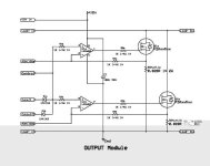
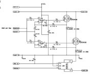
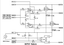
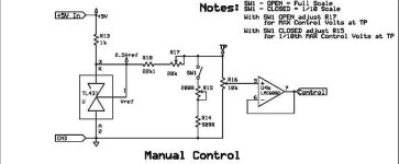
OK, the linear principal is simple enough I can see now. So everything to the right of the amp adjust pot (aka voltage reference) will be repeated for each FET used, is this right?
So one of the PIC's would be used as the voltage reference instead of much of the left part of the circuit, is this the idea?
Well, I think I'll do like John suggested and start to draw up what a switched cell analyser/load would look like. My problem is trying to keep out cool feature ideas when I work on a project... If it works out, Doc will be able to pump at least 100A out of small module, and into any homebrew load of appropriate resistive value. I think I have some good low voltage FETs to start out with and all the other parts I would need too. And I won't go layout crazy like I do with my controller, and instead slow down switching speed a bit to make designing the PCB simpler. And 5V will be much easier than the ~65V I'm used of, so this also should help.
As for PICs, I'm looking into which one to use, but I remember that there is one with SMPS (switching mode power supply) oriented peripherals.
I'll post when I've worked out the basic feature set and maybe a gross schematic too.
Let the linear vs digital showdown commence! :wink:
Pat
So one of the PIC's would be used as the voltage reference instead of much of the left part of the circuit, is this the idea?
Well, I think I'll do like John suggested and start to draw up what a switched cell analyser/load would look like. My problem is trying to keep out cool feature ideas when I work on a project...
As for PICs, I'm looking into which one to use, but I remember that there is one with SMPS (switching mode power supply) oriented peripherals.
I'll post when I've worked out the basic feature set and maybe a gross schematic too.
Let the linear vs digital showdown commence!
Pat


