kZs0lt
100 W
Hi,
I am fairly new to ebike & controllers, but decided to take the hard way and make myself the controller, because it can be fun.
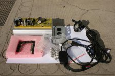
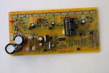
I ordered a 12 FET board from keywin and planning to populate with 4110 FETs. Also got the USB to Serial port cable for programming and a thumb throttle.

This is supposed to be the 600w version with power resistors set for 48 volt, 220, 330 and 680 ohms. Keywin said the LVC is set at 41.5v.

View attachment 3
However he forgot to provide the aluminum FET mounting bar.
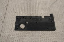
I tried to get something similar locally but I had no luck, so I made one from the aluminum plate I found around my house:

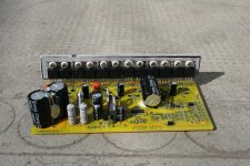
Soldered the FETs:

And wired the phase, the halls, throttle, battery main and ignition wires.
I have only 2x3s Lipos 4Ah, so I wanted to set the LVC for 20v initially and later get it higher once I get more battery. But I failed to program the board, don't know what I am doing wrong.
I've downloaded the program and installed the .ocx files, installed a USB to serial driver I found, and hit the magic transmit button, touch the board with the connector, and still nothing. What am I doing wrong? What driver are you using and how can I check if my USB adapter is really working?
Next I tried to hook up the controller to the motor. I used a DC current source with ~35v and put 3s lipo in series, so that it gave around 47-48v.
I get a big spark on turning it on, but nothing happens when I hit the throttle. I measured the throttle signal and it was between 0.47-4.3v, the halls from 0v to 5v and the bus voltages look OK. I checked 2 motor phase combinations with every 6 halls combination and no movement from the motor, there is no current on the high current side.
What I am possibly doing wrong? What should I measure to get to the problem, any ideas?
Waiting for your ideas, thanks for the help in advance,
Zsolt
I am fairly new to ebike & controllers, but decided to take the hard way and make myself the controller, because it can be fun.
I ordered a 12 FET board from keywin and planning to populate with 4110 FETs. Also got the USB to Serial port cable for programming and a thumb throttle.

This is supposed to be the 600w version with power resistors set for 48 volt, 220, 330 and 680 ohms. Keywin said the LVC is set at 41.5v.

View attachment 3
However he forgot to provide the aluminum FET mounting bar.
I tried to get something similar locally but I had no luck, so I made one from the aluminum plate I found around my house:

Soldered the FETs:

And wired the phase, the halls, throttle, battery main and ignition wires.
I have only 2x3s Lipos 4Ah, so I wanted to set the LVC for 20v initially and later get it higher once I get more battery. But I failed to program the board, don't know what I am doing wrong.
I've downloaded the program and installed the .ocx files, installed a USB to serial driver I found, and hit the magic transmit button, touch the board with the connector, and still nothing. What am I doing wrong? What driver are you using and how can I check if my USB adapter is really working?
Next I tried to hook up the controller to the motor. I used a DC current source with ~35v and put 3s lipo in series, so that it gave around 47-48v.
I get a big spark on turning it on, but nothing happens when I hit the throttle. I measured the throttle signal and it was between 0.47-4.3v, the halls from 0v to 5v and the bus voltages look OK. I checked 2 motor phase combinations with every 6 halls combination and no movement from the motor, there is no current on the high current side.
What I am possibly doing wrong? What should I measure to get to the problem, any ideas?
Waiting for your ideas, thanks for the help in advance,
Zsolt


