
You are using an out of date browser. It may not display this or other websites correctly.
You should upgrade or use an alternative browser.
You should upgrade or use an alternative browser.
12 kw rc motor
- Thread starter markobetti
- Start date
SplinterOz
1 kW
dangerzone said:Arlo1 said:I have an order in for a sevcon G8055. I will run collossus with a sevcon and eventualy rewind it for max effieciency.
With the second collossus I am still going to rewind as a 9 phase so I need one more 24 fet bord and one more 36 fet bord to build my 3 bord 9 phase controller!
So if anyone has a 24 fet kit or 36 fet kit or pcb please let me know.
Thanks.
I layed up 4 of 5 peices of Carbon fiber bodywork last night for the YSR and should have it finnished by the end of the month. I am in ottowa till the 17th so I hope to have a pacage or two to pick up when I return home so I can finish my Kickass E-ysr build!
What is the max rpm of the G8055..?
I found an older manual online http://www.quadmotion.se/...Sevcon48V/Gen4_Product_Manual_V2.2.en.pdf it is a slightly older version but should be ok.
I have read a section that tells us the electrical RPM of the motor....
Motor speed sensor (encoder)
A 4-wire connection is provided for open-collector or current-source encoder devices (software configurable). You can use the following types of encoder, or equivalents: Type Output Supply Specification
Bearing Type
(SKF and FAG) Open collector 5 to 24 V DC 64 and 80 pulses per revolution Dual quadrature outputs Output low = 0 V (nominal)
HED Type
(Thalheim) Constant current 0 V nominal 80 pulses per revolution Dual quadrature outputs Output low = 7 mA Output high = 14 mA
The number of encoder pulses per revolutions
") and the maximum motor speed (N) are related to, and limited by, the maximum frequency of the encoder signal (fmax). The following table shows the maximum motor speed for a given encoder on a 4-pole motor. Encoder ppr Maximum motor speed (rpm)
and the maximum motor speed (N) are related to, and limited by, the maximum frequency of the encoder signal (fmax). The following table shows the maximum motor speed for a given encoder on a 4-pole motor. Encoder ppr Maximum motor speed (rpm)128 6000
80 10000
64 10000
For other types of encoder and motor use the formulae:
fmax(hz) = n(per rev) * rpm / 60
with fmax limited to 13.3 kHz.
So the Colossus has 10 pole pairs and 3 sensors (so n is either 30 or 60)
So I get fmax = 30 * 6000 / 60
so fmax = 3,000 Hz (or 3kHz)...
could this be right???
SplinterOz
1 kW
Updated manual here... http://electricboatdesign.com/wp-content/uploads/2010/11/Gen4-Product-Manual-V3.0.pdf
Pages 5-10 and 5-11 cover the Hall sensors in better detail than the last version.
Thanks
Tony
Pages 5-10 and 5-11 cover the Hall sensors in better detail than the last version.
Thanks
Tony
Thanks Splinter, I have been to buisy trying to do other things to get the bike ready to find the proper manual.
I installed the taperlock sprocket yesterday and to get the chain to line up to the sprocket I had to cut a tab off my bracket and today I will reweld it I tried to leave lots of room to move the bracket back and forth because I didn't have the taperlock when I made it but the taperlock is a industrial peice and it takes a lot of room...
Non the less it should be mounted with a chain tonight. Then back to the carbon fiber!
I installed the taperlock sprocket yesterday and to get the chain to line up to the sprocket I had to cut a tab off my bracket and today I will reweld it
Non the less it should be mounted with a chain tonight. Then back to the carbon fiber!
Nuts&Volts
100 W
@Algar123 - it is still in testing, but according to some recent posts they should have some news sometime this week. Hopefully we'll hear some good news soon!
Biff
100 W
I have been using a Sevcon Gen4 recently (not for this motor, but another low inductance / resistance motor). I can say that the Sevcon does not like to operate over 660Hz, it does not like low inductance that much either but it doesn't blow up. It might work up to 800Hz, but you will probably need help from a sevcon technician to get the control parameters right, and the control at those speeds will be rather rough (think pulses of plus or minus 100 Amps from the desired current). This will definatly take some time to configure on a Sevcon, you will not be able to just hook it up and make it work, you will need to program it very carefully. I might be able to help getting the sevcon working with this motor, and then share the Device Configuration File or parameters for those of you who are interested.
-ryan
-ryan
Programing things with a computer is my favorite part.Biff said:I have been using a Sevcon Gen4 recently (not for this motor, but another low inductance / resistance motor). I can say that the Sevcon does not like to operate over 660Hz, it does not like low inductance that much either but it doesn't blow up. It might work up to 800Hz, but you will probably need help from a sevcon technician to get the control parameters right, and the control at those speeds will be rather rough (think pulses of plus or minus 100 Amps from the desired current). This will definatly take some time to configure on a Sevcon, you will not be able to just hook it up and make it work, you will need to program it very carefully. I might be able to help getting the sevcon working with this motor, and then share the Device Configuration File or parameters for those of you who are interested.
-ryan
Life is boring if things come to easy! :wink:
:Edit: Im not saying Im not interested in your help! I will almost deffinatly need your help!
Nuts&Volts
100 W
Biff I would definitely be interested in that solution down the road when these motors are available
What exactly is limited to 660HZ? is that the switching of the phases? So the motor could be run at 6600RPM (660Hz*10polepairs)
Thanks
Kyle
What exactly is limited to 660HZ? is that the switching of the phases? So the motor could be run at 6600RPM (660Hz*10polepairs)
Thanks
Kyle
Biff
100 W
Nuts&Volts said:Biff I would definitely be interested in that solution down the road when these motors are available
What exactly is limited to 660HZ? is that the switching of the phases? So the motor could be run at 6600RPM (660Hz*10polepairs)
Thanks
Kyle
660Hz is electrical frequency of the phases. RPM = Freq * 60 / poleparis.
for a 20 magnet motor (10 pole pairs) that would be
660* 60 / 10 = about 4000 RPM
above that your running gets rough because there are not enough PWM pules per cycle.
-ryan
At the higher rpm the short PWM is not as crutial so is it possible to step it down to less pwm??????? I want my motor to spin 7000-8000 rpm!Biff said:Nuts&Volts said:Biff I would definitely be interested in that solution down the road when these motors are available
What exactly is limited to 660HZ? is that the switching of the phases? So the motor could be run at 6600RPM (660Hz*10polepairs)
Thanks
Kyle
660Hz is electrical frequency of the phases. RPM = Freq * 60 / poleparis.
for a 20 magnet motor (10 pole pairs) that would be
660* 60 / 10 = about 4000 RPM
above that your running gets rough because there are not enough PWM pules per cycle.
-ryan
Hey Ryan
I can't help but wonder what the chances of using a step up or down transformer hooked to each phase???? Give the fets a Higher amount of inductance to work with. For instance have a set of 10x step down transformers for starting out so the controler would have 10x the resistance then once you are up to speed a bit have some relays switch off the transormers and run the phases from the controller right to the motor!
I can't help but wonder what the chances of using a step up or down transformer hooked to each phase???? Give the fets a Higher amount of inductance to work with. For instance have a set of 10x step down transformers for starting out so the controler would have 10x the resistance then once you are up to speed a bit have some relays switch off the transormers and run the phases from the controller right to the motor!
SplinterOz
1 kW
Ok so this is not good news.... My motor has already spun up past 6,000 no load and I expect over 5,000rpm under load. Now that is with a 72volt pack. The prototype is mechanically limited by the skirt bearing to about 8,000, however the prod model should do 14,000rpm (if you give it the volts.)
Now I am really wondering if this is the right controller?
Now I am really wondering if this is the right controller?
If I ever get one in my hands I will let you know. :wink: Meen while I will keep pushing forward and rewind one motor as a 9 phase, or 3 seprate 3 phase motors to be more acurate.SplinterOz said:Ok so this is not good news.... My motor has already spun up past 6,000 no load and I expect over 5,000rpm under load. Now that is with a 72volt pack. The prototype is mechanically limited by the skirt bearing to about 8,000, however the prod model should do 14,000rpm (if you give it the volts.)
Now I am really wondering if this is the right controller?
markobetti
10 kW
- Joined
- Jul 16, 2009
- Messages
- 620
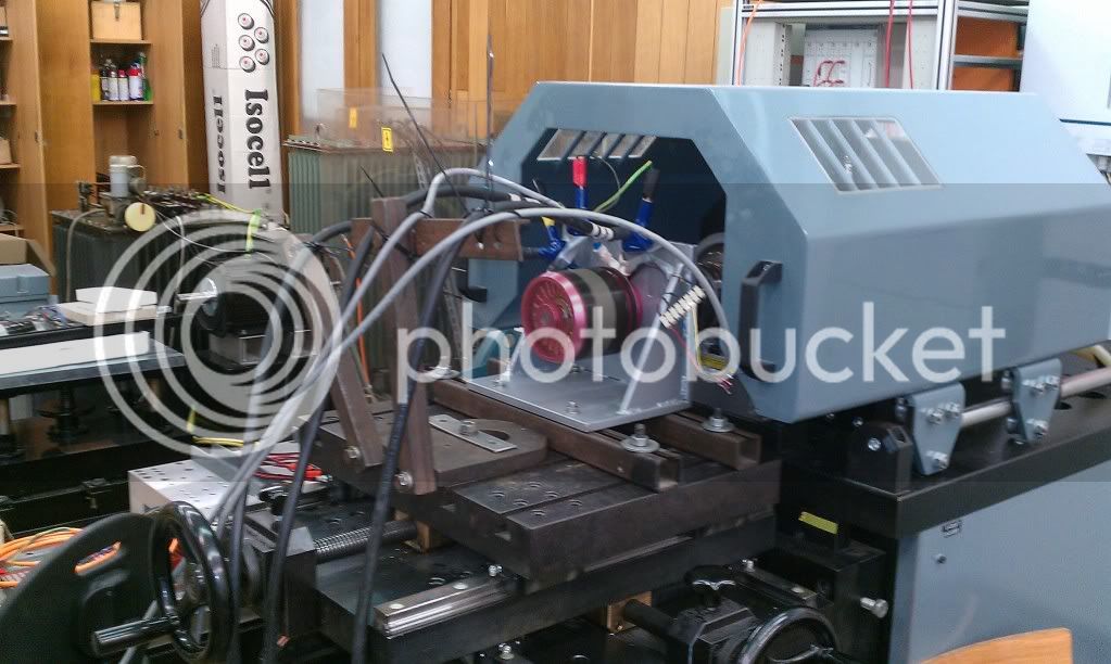
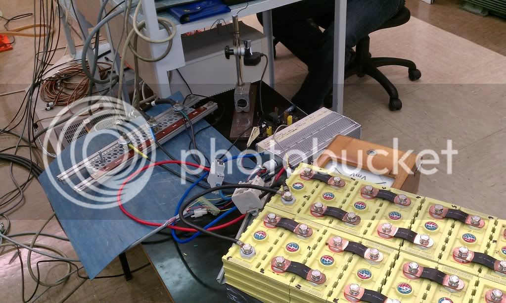
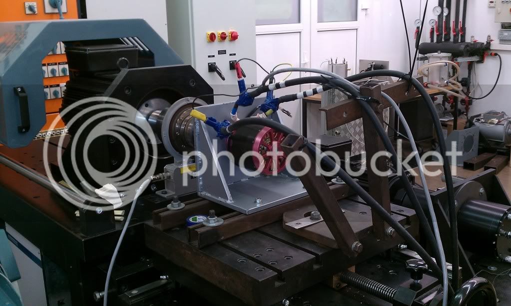
Got to thank Grga and accountant for finding time to take Colossus LQC for first series of test in facility . Decent results . Controller: 36 fet- Done by Grga , Colossus LQC - Hals second version . This are pictures. The second test is planned also this month. After all things are calculated and we will see the math behind the motor. I Just wanted to let you guys know we are not kidding and that this project is still on fire..
SplinterOz
1 kW
Sooooo cool... can't wait to see the results... Definitely seems like you are putting some serious load on the motor.
Biff
100 W
Arlo1 said:Hey Ryan
I can't help but wonder what the chances of using a step up or down transformer hooked to each phase???? Give the fets a Higher amount of inductance to work with. For instance have a set of 10x step down transformers for starting out so the controler would have 10x the resistance then once you are up to speed a bit have some relays switch off the transormers and run the phases from the controller right to the motor!
That seems like something that might work. I don't think that a transformer would be the way to go to get the best performance out of a machine, it is probably best to build a controller to handle the machine in the first place, but it could give you great torque at startup and high speed with the controllers that are currently available. I think you would still have all the same controller issues you have with a series/parallel switching machine, where the controller would need to know when you were about to make the switch, otherwise it would think that something is seriously wrong with the motor and shut down.
One thing to remember is resistance felt by the input circuit is related to the square of the step up ratio. Power on both sides of a transformer is the same, and power = V^2/R , now assume you have a 2 times step down transformer (essentially halving the kV of the motor so you could input 100V 20A rather than 50V 40A at the Same RPM / Power). So if your resistive load on the secondary is R, and voltage on the Secondary is V, your output power is V*2/R, and your input power would have to be the same but the voltage would be 2V (as defined by the step up Votlage) so the resistance the input side "felt" would be 4R ( V^2/R = (2V)^2/(4*R) ). I don't think that changes your logic at all, infact it might make it even more attractive. The only bad side is that the transformers are like big inductors and would take up space and power, but they could be used to make that "series/parallel" switch work for any brushless motor externally.
-ryan
How about just wrapping the motor cables around some ferrite cores? It will add inductance in series and help the controller but doesn't need to add much losses. It is sometimes done with ironless motors for the same reason. Also, a y/d switch would be nice, but mainly for performance reasons. Can all six end windings be easily accessed and extended to the outside of the motor?
Simply put you dont gain performance with wye delta you just take stress off your controler!crap said:How about just wrapping the motor cables around some ferrite cores? It will add inductance in series and help the controller but doesn't need to add much losses. It is sometimes done with ironless motors for the same reason. Also, a y/d switch would be nice, but mainly for performance reasons. Can all six end windings be easily accessed and extended to the outside of the motor?
Unless the controller is so powerful it can push the motor torque to the limit in delta termination, being able to switch to y termination at low speeds will enable an increase in torque. Switching back to delta at higher rpm's will restore the rpm capability. A y/d switch should act about the same as a gearbox, unless (like i said) the controller is already powerful enough to push the motor to it's very limits. Seems like something with potential to increase performance...
No for the same given amps and volts WYE and DELTA produce the same torque!crap said:Unless the controller is so powerful it can push the motor torque to the limit in delta termination, being able to switch to y termination at low speeds will enable an increase in torque. Switching back to delta at higher rpm's will restore the rpm capability. A y/d switch should act about the same as a gearbox, unless (like i said) the controller is already powerful enough to push the motor to it's very limits. Seems like something with potential to increase performance...
nieles
10 kW
sorry to say it arlo1 but i think your statment is not true.. KT (torque constant) is inversely proportional to KV. the delta/wye difference is sqrt3 (1.73).
the output watts for both motors would be the same (if the efficiency is the same)
but the delta motor has 1,73 times more rpm than the wye motor
the wye motar has 1,73 times more torque than the delta motor
the output watts for both motors would be the same (if the efficiency is the same)
but the delta motor has 1,73 times more rpm than the wye motor
the wye motar has 1,73 times more torque than the delta motor
Nope it is 100% correct!nieles said:sorry to say it arlo1 but i think your statment is not true.. KT (torque constant) is inversely proportional to KV. the delta/wye difference is sqrt3 (1.73).
the output watts for both motors would be the same (if the efficiency is the same)
but the delta motor has 1,73 times more rpm than the wye motor
the wye motar has 1,73 times more torque than the delta motor
As quoted by luke.
" For the same battery amps and battery volts its identical. But Delta puts 1.7 times more load on the FETs"
So WYE does not give you 1.73 times more torque it just makes it 1.73 times eiser on the FETs!
Similar threads
- Replies
- 3
- Views
- 805
- Replies
- 10
- Views
- 1,586
- Replies
- 12
- Views
- 10,887