12s8p charging configuration advice?

Definitely hard to identify a bad cell in a parallel string. That's why I suggested 4p sections, connected by a wire you can snip and reconnect easy, so you can identify it down to 4 cells to remove from the pack.

I'd highly recommend building it as modular as possible, so if you need to remove a section you can do it fairly easy. 4P spot welded, 6s welded, Or the same soldered. The idea being that a suspect section can be removed, and replaced with one you have ready to go fairly easily.

Then at your leisure, you can dig into the section to find a bad cell. If you don't have enough cells for spares, build 7P.

Each 4-6 cell section can be tested and passed before final assembly into a huge pack! Especially if you solder, you can set aside any section that might have had a cell ruined in the soldering.

Shitloads of practice, before you start soldering round cells. It must be done very fast from what I hear.
 
kristafervale said:
I can do either weld or soldier was planning on soldier because:
1.) I'm new but understand heat to be a major issue with batteries
2.) The spot welder I'm planning on using is a DIY I made since I can't afford / justify the price of a new one yet.
3.) I've never used a spot welder before.
4.) If a cell goes bad I figured UN-soldiering would be easier.

Totally appreciate all the advice and even the series vs parallel debate is informative thanks everyone!

here's how i do it. less than 1 second actually...

[youtube]0ZRwMXL-Rvs[/youtube]
 
kristafervale said:
That's a nice technique, what's the bar in the middle? 8ga solid wire?

13CWsjB.jpg


12ga
 
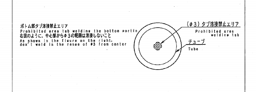
do not solder or spot weld in the center of the bottom of the case. solder the wire to the edge of the bottom of the case. do not connect the cans in parallel first. connect in series and then connect the packs together in parallel through the sense wires.

all you do by soldering a large wire to the middle of the bottom of the case is shorten the life of the cell. there is a reason the manufacturers warn not to spot weld or solder there in the middle.
 
overclocker just do it put some sense wires on it for your cell checker and run it. Just monitor it. Run it. Depends how many AH you take out of it. You can be the BMS for it, just check it. Or BMS it. Leave 30% or more in the tank. Oh did I say monitor it ?
Plus C.A or watt meter.
 
999zip999 said:
overclocker just do it put some sense wires on it for your cell checker and run it. Just monitor it. Run it. Depends how many AH you take out of it. You can be the BMS for it, just check it. Or BMS it. Leave 30% or more in the tank. Oh did I say monitor it ?
Plus C.A or watt meter.

yep i've had over a thousand kms with it already. so far so good...
 
dnmun said:
do not solder or spot weld in the center of the bottom of the case. solder the wire to the edge of the bottom of the case. do not connect the cans in parallel first. connect in series and then connect the packs together in parallel through the sense wires.

all you do by soldering a large wire to the middle of the bottom of the case is shorten the life of the cell. there is a reason the manufacturers warn not to spot weld or solder there in the middle.


omW8OUx.png


yep i remember posting this a few months ago. but i still could not find the ACTUAL reason why not to weld there. any ideas?
 
the negative current collector has all of the negative electrode tabs ultrasonically welded to it on the bottom end of the mandrel that the jelly roll is wrapped around.

when the can is assembled the mandrel is pushed down from the top where the positive current collector is on the top end of the mandrel and the anode cap is then pushed down hard enuff to hold it as the anode cap is locked in place by the end cap crimping machine.

when you spot weld to the center of the bottom of the case then the gasses formed inside by the heat will cause the negative current collector be become detached from the case. aimho.
 
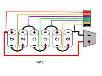
So after going back and forth all weekend I think I landed on making 6s1p groups and then building a couple of different wiring harnesses.
One harness for charging and one for discharging (riding the bike).

Can you guys give me your opinions on these schematics? I think I've got it right but I want to be sure before I start soldiering.

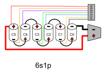
First what each of the 6s1p will be:
6s1p Schematic.png

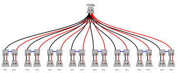
The discharge (riding the bike) wiring harness:
Wiring Harness Schematic.png

Until I do more research on bulk chargers and BMS, I plan to not use the bike much except in testing.
I'll use the Imax charger to balance the individual 6s1p's for now.

Once I'm more confident (and knowledgeable), I think I ought to be able to get a decent bulk charger and a 12s capable BMS and charge the whole pack, but I need to crawl before I run.

Opinions and critiques definitely appreciated!
 
If I read your diagram right. It's wrong. I Think I could be wrong.
The way I see it.
Bo to co neg.
B1 to co pos.
B2 to c1 pos.
B3 to c2 pos.
All the next wires to pos.
I think I'm right. ???
 
You see the problem with 12s8p instead of 8p 12s. How to hook up the many sense wires and monitoring. A hobby that harder on each cell leading to failure to each. But easr to isolate and replace as you will need to replace more often. Unless you use high quality cell like A123 or Samsung 20r. ect
 
I don't think I understand what you're saying but I updated the drawing to hopefully clarify where I THINK the balance leads should be.

6s1P.png
 
Back
Top