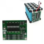
A working BMS with no cells outside it's limits shouldn't drop any voltage across the FETs except when current flow is high enough for that FET's internal resistance to do so via ohm's law. You can measure votlage across the FETs' source and drain pins to see if this is happening and if hte voltage dropped there plus your measured pack output voltage adds up to the total cell block voltage.
What voltage are each of the cells *now*?
What happens if you place a load on the output of a pack that reads low, while measuring it?
If it drops to nothing, the BMS turned off the output to protect the cells against a fault; you'd have to verify wiring, voltages, balance, etc., to see which thing is outside the BMS limits and correct that.
If it stays at the present voltage, then the BMS output is not turned off, but it could have tried to and failed:
Are the BMSes common-port or separate-port? (CP uses only one connection for charge and discharge)
The former requires the packs to be separated at the second set of ports whenever the first are being used, and vice-versa, so the BMS can actually protect the cells.
Are your BMSes designed to operate at the full system voltage? Or only at the individual pack voltage? If the latter, the FETs may be damaged by the full system voltage placed across them whenever they turn off the output or input for any reason. There are ways to work around that with diodes, posted by Fechter in the many various threads about seriesing battery packs, but if they are already damaged you'd have to replace the BMSes first with working ones. When damaged, usually the FETs fail stuck on (shorted) and the BMS can no longer protect the cells by turning off the output or input (depending on which set failed).
Other notes:
A 3s pack won't be high enough voltage when full for a typical "12v" range, which would normally be 13.6-14.4v for lead-acid SLA replacements. So the system may not have as much power/torque or go as fast as it did with the SLA at full charge. (A 4s pack is too high a voltage when full; some 12v systems will be damaged by the 16.8v full voltage of this).
A controller with an LVC designed for SLA should turn off around 10v minimum, might turn off as high as 11-12v. So a 3s pack will still have a lot of energy in it when the controller shuts off.
(if your controller has no LVC, then the last doesn't matter, but you're depending on the BMS to protect the cells, and that should be the second line of defense, not the first--running a pack to BMS LVC every time is hard on the cells and means that if the BMS can't turn off the output for any reason, you'll overdischarge the cells because you won't know it's empty until too late. )
Normally LiFePO4 cells are used in 4s for SLA replacements, because they pretty closely match the voltage range, and eliminate the above issues (except for the very last one; that depends on the controller having a working LVC above the BMS LVC).


