18650 battery pack build Kepler style

Dear Kepler

2015-01-25 22.27.27 (3).jpg

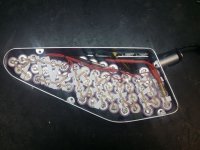
Thanks for your help. Paul did supply me with a BMS, photo attached. Following your photos, the black lead will be attached to the battery negative and the blue lead to the controller. It seems that you have another smaller but still high current black lead that is connected (I think) to the BMS in the area of "your" yellow lead (my equivalent lead is black and I'm not sure what its for). I also don't have the red lead to be attached to the positive terminal of the battery.

Could you help me out a bit here ? I'm only a simple finance man.

Thanks in advance, Mike
 
Red from the battery goes directly to the controller (no direct connection to the BMS).

There are two 10# wires (Black and Blue) on the bottom of the BMS. Black goes to the battery negative and the blue goes to the controller negative.

The charge lead has its positive connected directly to the battery positive and its negative going to the top 12# BMS wire. In my case it is yellow. In your case it is black.

Home that makes sense :)
 
Thanks all again for the positive comments. Much appreciated.

KARCH67, the only thing i would do differently is install insulating gaskets on the positive battery terminal of each cell before soldering.
 
Kepler said:
Thanks all again for the positive comments. Much appreciated.

KARCH67, the only thing i would do differently is install insulating gaskets on the positive battery terminal of each cell before soldering.
That is interesting. I've had a quick look at the Panasonic NCR18650PF cells I'm using and the cell's own gasket seemed to be card rather than plastic. I didn't take one apart to see properly, but might this be possible? Plus I'm spot welding rather than soldering.

Michael
 
Man, I've been looking at those pictures for hours. I keep seeing groupings of 8 and two of 4 where the neg and pos bullets are. My dumb brain can't seem to wrap around how the 14s comes into play. Anyone else as thick? So HTH does it work?
I just can't grasp the 14 connection.
At this rate I better stick to buying configured packs...


What the heck and how the heck.
 
Hi Tom,

Its really quite simple. The pack is a 4P (4 cells in parallel) and then 14 of those paralleled groups connected in series to create 14S.

The picture below is a single 4P group with all 4 cell's connected across their positive terminals and across their negative terminals.

Think of each 4P group now as one large capacity cell. Each single cell was 3.6V nominal and 2.9 Ahrs (depending on what type of cell you are using.) As a paralleled group, it is now 3.6V nominal but now has a capacity of 11.6 Ahrs.

You need to make 14 of these. Once you have made 14 of these, you then need to connect them all together in series. So this means connecting the positive terminal group of each 4P pack to the negative of the next 4P pack. Keep doing this until all 14 of the 4P packs are connected togther. You will end up with a 50.4V nominal pack (14 x 3.6V = 50.4V) hot off the charger it will be 58.8V.

Hope that clears it up for you. :)
 

Attachments

  • 4P.png
    4P.png
    3.3 KB · Views: 5,217
Thanks, it took a picture. :oops: NOW it makes sense. Thanks, again! Embarrassing simple...
 
3 month report:

Very little follow up data on 18650 packs that have been soldered together as opposed to spot welded so thought I would post my experiences to date.

Pack has logged 55 cycles so far.
Pack has always been charged with a 2A charger through the BMS.
Pack spend most of its time around 500W load when riding.
Typically use around 5ah per ride.

Last week I pushed the the pack range to its maximum to see what sort of capacity the pack really had. Below is the data from the CA.

20150322_165309.jpg

20150322_165257.jpg

20150322_165350.jpg

20150322_165327.jpg

This was a hard ride which included a lot of hill climbing. For those familiar with the Dandenong Ranges here in Victoria, the ride included the 1 in 20, Devil's Elbow, The Wall, and Sky High tourist road. I used PAS only for the entire ride set to 250W.

I have my drive set to 43V cut out at at the end of this ride, I hitting the cutout underload so 3.1V per cell.

Pack managed a solid 10ah which I was very happy with. Opened up the case and measured each parallel group. all groups were within .05V of each other.
 
Kepler said:
No I am just relying on the gasket built into the battery. The built in gasket and heat shrink give a double layer of insulation which providing it isn't heat damaged through the soldering, should be fine. I think an extra gasket would have been a good precaution though and would certainly consider using them next time. I have rechecked all solder bridges this afternoon just incase. All good :)

Bingo! Assuming you were using LG D1's, as I did, that insulation is not good.
After few rides with my brand new pack, I had to come back home, because CA showed voltage dropping so fast.
As soon as I walked into my apartment, one of the cells at the very end of this pack started to smoke, and just blew up with huge amount of smoke.
Lucky for me, it didn't spread to the other cells around it.
Learned my lesson.
Will be definitely using plastic/paper round spacers for my next battery.

24dk8l1.jpg
 
LSBW said:
Kepler said:
No I am just relying on the gasket built into the battery. The built in gasket and heat shrink give a double layer of insulation which providing it isn't heat damaged through the soldering, should be fine. I think an extra gasket would have been a good precaution though and would certainly consider using them next time. I have rechecked all solder bridges this afternoon just incase. All good :)

Bingo! Assuming you were using LG D1's, as I did, that insulation is not good.
You can get 50pack of 18650 gaskets for $1.30 delivered on fasttech.
https://www.fasttech.com/products/1425/10012815/2157501
 
LSBW said:
Kepler said:
No I am just relying on the gasket built into the battery. The built in gasket and heat shrink give a double layer of insulation which providing it isn't heat damaged through the soldering, should be fine. I think an extra gasket would have been a good precaution though and would certainly consider using them next time. I have rechecked all solder bridges this afternoon just incase. All good :)

Bingo! Assuming you were using LG D1's, as I did, that insulation is not good.
After few rides with my brand new pack, I had to come back home, because CA showed voltage dropping so fast.
As soon as I walked into my apartment, one of the cells at the very end of this pack started to smoke, and just blew up with huge amount of smoke.
Lucky for me, it didn't spread to the other cells around it.
Learned my lesson.
Will be definitely using plastic/paper round spacers for my next battery.

Not good. Glad it didn't cause any major damage though.

I ended up insulating all positive bridges with a piece of cardboard. Not the prettiest solution but effective all the same. Luckily the solder wick bridge's had some flexibility in them to get the cardboard underneath them.
 

Attachments

  • 20150322_163331.jpg
    20150322_163331.jpg
    52.3 KB · Views: 4,878
That was discussed early in the thread. But sourced after the build.
 
Hi everybody !

Kepler : Do you battery is still okay ?
I'm gonna make my own battery pack soon ( I'm just waiting for the batteries haha ) but Im thinking about a copper wire (like electric wire for house) and when I saw your post, desoldering tape ...

With copper wire, I'm sure it's good because 16-14AWG but for the soldering tape, no information about how many amp we can provide through this tape.

Thank you !


edit : It's too late but for those who want to insulate, I'm gonna use round paper AND Kapton tape : http://www.ebay.fr/itm/Kapton-tape-High-Temperature-10mm-x-33M-for-BGA-/221018518931?pt=LH_DefaultDomain_0&hash=item3375baf593 it's really cheap and useful for big battery pack.
 
Hi Kepler
I am new to the forum and just installed the bafang 750w bbs02 running on Paul's 50v, 16.5ah, 29e battery.
After more than 3 weeks of reading the bafang and bafang program threads, I had started to program my controller with your specs and love it.
Just wanted to say a thank you for sharing your experience with us noobs.
By the way love your builds and wish I had your skills.
One quick question can someone pls explain to me why are those paper gaskets so important.
From my understanding the battery wouldn't move, it's all glued together, so I thought there is little chance for it to short out.
Pls help a noob understand your theory.
Cheers and love to see more of your build.
 
individual cell casing is negative and the cell positive terminal on the top could potentially short to the negative case if the braid conductor was deformed enough to contact the cell case edge on the top of the cell. The paper prevents the braid conductor from contacting the cell case at the top of the cell. Short circuits are not productive and potentially dangerous :mrgreen:
 
dbaker said:
individual cell casing is negative and the cell positive terminal on the top could potentially short to the negative case if the braid conductor was deformed enough to contact the cell case edge on the top of the cell. The paper prevents the braid conductor from contacting the cell case at the top of the cell. Short circuits are not productive and potentially dangerous :mrgreen:
Thanks dbarker that make sense now :D
 
Totally dangerous, it could be making explode and catch in fire the battery and/or the battery pack ...
The plastic is really thin and the conductor (wire or nickel plate) can heat, then melt the thin plastic.
You can see here the + and the - (yes the minus is not only at the bottom but it's the battery's case !)
AB6y65v.jpg
 
alexis57 said:
Hi everybody !

Kepler : Do you battery is still okay ?
I'm gonna make my own battery pack soon ( I'm just waiting for the batteries haha ) but Im thinking about a copper wire (like electric wire for house) and when I saw your post, desoldering tape ...

With copper wire, I'm sure it's good because 16-14AWG but for the soldering tape, no information about how many amp we can provide through this tape.

Thank you !


edit : It's too late but for those who want to insulate, I'm gonna use round paper AND Kapton tape : http://www.ebay.fr/itm/Kapton-tape-High-Temperature-10mm-x-33M-for-BGA-/221018518931?pt=LH_DefaultDomain_0&hash=item3375baf593 it's really cheap and useful for big battery pack.

Yes battery is still operating perfectly. Best pack I have ever used. I keep the draw down to 600W max and can confidently get a true 10ahr out of the pack.
 
Oic20v said:
Hi Kepler
I am new to the forum and just installed the bafang 750w bbs02 running on Paul's 50v, 16.5ah, 29e battery.
After more than 3 weeks of reading the bafang and bafang program threads, I had started to program my controller with your specs and love it.
Just wanted to say a thank you for sharing your experience with us noobs.
By the way love your builds and wish I had your skills.
One quick question can someone pls explain to me why are those paper gaskets so important.
From my understanding the battery wouldn't move, it's all glued together, so I thought there is little chance for it to short out.
Pls help a noob understand your theory.
Cheers and love to see more of your build.

Glad you have found the info useful. I still use those settings and are close to 10000km on this drive.

In regards to the hot gluing, the glue can crack so dont rely solely on the glue to keep the cells together. Mine are tightly packed in the aluminium case and well supported with insertion rubber.
 
Back
Top