First eBike build with longevity in mind - Samsung 50G MTB Front Hub (Now rear hub)

Sajeel

100 mW
Joined
Jul 28, 2022
Messages
37
Location
Copenhagen, Denmark
Hello Endless Spherers!

I've had a 48v 1000W kit conversion kit laying around for 2 years (Aliexpress). I sold my car and now I'm looking to do my first eBike build!

Originally I planned on making a sleeper dutch bike, but I have lowered my own expectations due to difficulties finding a suitable bike for a 27,5" hub motor wheel.

Donor bike
I bought a cheap brand new (ladies)MTB bike for ~300 euros new:


As the MTB was relatively cheap, I was expecting the front suspension fork to be made of steel as I have read on the forums that aluminium forks are a death trap, eventho I have seen people on the forums make it work with 500W+ motors without issue.
I did a magnet test on the fork - unfortunately it seems to be made of aluminium.
I've decided to go forward with the project anyways, as I have not been able to find a cheap steel front suspension fork from an EU supplier - I have no knowledge about size and fitting, installation etc. More on that later!

Battery housing
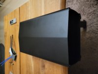
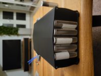
The battery will be housed in a rear-mounted battery rack:


I have asked the supplier - it will fit a 13S6P 21700 configuration.
I will be using Samsung 50G 21700 cells @ ~4800 mAh for value. Impressive cycle life @80 % capacity after 1000 cycles. (Ordered from EU-based Endless Sphere member turmich - see his selling thread of many different cells and packs here)

Cycle life of batteries
I plan on pushing the cycle life of the battery pack even further, based on a NASA study of 18650 cells showing LG MJ1 cells retaining 97 % capacity after 500 cycles (rated originally as 400 cycles @ 70 % capacity) when using a discharge cut-off at 3.0v and charge cut-off at 4.1v.

I understand that different cell chemistry will behave differently and under different conditions, and that I can't expect the same results in the study. However I would imagine that it would have a somewhat comparable effect.
Therefor I plan to charge my pack @ 0.33C (~1.5A - ~1.6A).

Battery pack
For the battery pack I have been considering three options:

1. 13S6P - 28.8 Ah. At 3v discharge cut-off and 4.1v charge cut-off for each cell it's probably 10% less capacity(?) ~26 Ah

2. 14S5P (overvolted by default at full charge to 4.1*14=57.4v) 24 Ah. At 3v discharge cut-off and 4.1v charge cut-off for each cell it's probably 10% less capacity aswell(?) ~22 Ah

3. 14S5P (undervolted each cell to 3.9v making package voltage the same as a 13S configuration due to easy/cheap charger solutions) I expect battery capacity to be 70 % of 24 Ah = ~17 Ah

Range calculations:
I estimate 15.6 Wh/km - based on numbers found on random websites. I am curious for references, if any of you guys have some numbers from your own experiences that would make this calculation more interresting and accurate then please feel free to share.

1. 26 Ah * 48v = 1248 Wh | 1248 Wh/ 15.6 Wh/km = 80 km range

2. 22 Ah * 50.4v = 1109 Wh | 1109 Wh/ 15.6 Wh/km = 71 km range

3. 17 Ah * 48v = 816 Wh | 816 Wh/ 15.6 Wh/km = 52 km range

I _only_ have 21 km to work, which is why I'm okay with a 0.33C charge rate.


Option 2 seems very appealing to me, since I will get more "umphf" when low on battery, compared to the other two options - the range compromise also seems decent. I am however thwarted a bit by finding a suitable and economically viable charging solution that will let me charge at 57.4V @ 1.6A or 1.5A as I only want to charge each cell to 4.1V. I've looked at "The Satiator" from Grin Technologies that I would feel comfortable with (allowing me to charge @ 58,8V to get a full balance charge every now and then aswell), but it is sooo expensive. Any input will be much appreciated.


Other things to consider
Cell stress in regards to amps will be higher with a 5P configuration vs. a 6P configuration.
The Samsung 50G cells standard discharge current (1C) is 4.85A. They are rated for 9.7A max(2C) with max pulse discharge of 14.55A (3C).
Conforming to 1C discharge I would be able to draw 24.25A from 5P and 29.1A from 6P.
The controller I have is rated for 15A continious - 30A +/-. It would be be inline with my goal for cycle life of the batteries.

Other things that are noteworthy to mention is that I have a cheap 13S BMS and a decent 14S BMS with bluetooth.


Hub motor on aluminium front suspension fork
This is a topic that I have done lots of research on, and rightfully so it seems. I would love to write this section, as I feel it will probably be most important to my own safety, but right now it's really late where I live, and so I leave you with your imagination.
I will update the thread tomorrow - hopefully with more pictures aswell.


Your efforts and input are much appreciated, thank you!

// Sajeel
 
Nice looking bike. I think I would do #2, but discharge to 3.2V, leaving the cutoff at 3.0V, if the range is still sufficient. If you're setting a hard cutoff at 3.0V, it will probably shut it down at 3.2V anyway, due to voltage sag.

What speed does the 15.6 Wh/km assume? You could look at the discharge curves for the cells and see where it starts falling off the cliff. Not much value in setting it lower than that. It also depends on how much you think you'll normally be pulling from the pack, which translates to sag.

Personally I don't like cutoffs, since it may shut down the bike when I need it the most, so I just monitor the voltage.
 
Sajeel said:
Originally I planned on making a sleeper dutch bike, but I have lowered my own expectations due to difficulties finding a suitable bike for a 27,5" hub motor wheel.
That's not too difficult to fix, by relacing the motor into the wheel size you need. (there are a number of threads on wheel building / lacing, etc should you wish to try this).

As the MTB was relatively cheap, I was expecting the front suspension fork to be made of steel as I have read on the forums that aluminium forks are a death trap,
They are not, as long as you are using proper torque arms so there is no torque applied to the dropouts themselves (as they are not designed to take any torque, and neither are the rear dropouts--that is also true of steel forks and frames, with the single exception of any frame designed specifically for IGH's that transfer their torque via axle flats to the frame, if there are any, and any frame specifically designed to clamp a hubmotor (or IGH) 's axle flats to do the torque transfer).

FWIW, I've never seen a commercially-available steel bicycle suspension fork that was any better--usually from worse, to much worse, than all the aluminum / etc forks I've dealt with. There probably is one somewhere...just havent' found it.

There are a number of tested alternatives for making aluminum forks work safely with hubmotors that transfer torque via the axle flats, from torque arms / plates to dramatic mods like removing the dropouts and using a tube with new clamping ones built on their ends. (the tube could be clamped on, glued on, etc).

A pair of Grin Tech v4 torque arms from http://ebikes.ca , one on each dropout, would probably be a perfectly acceptable solution.


Also note that generally, the cheaper something is, the lower it's quality, reliability, etc.

So looking for a cheaper steel suspension fork might not be the answer you really want--even if it's dropouts were any better (which isn't really all that likely, especially since most of the ones I've seen use "pinched" dropouts--they take the tube of the fork lowers and just squish it flat, then stamp/cut the dropout into that. Some even weld along the tips...some don't. (I forget whether the steel ones on my old DayGlo Avenger bike were welded or not...but I spun out a geared hub in them easily enough....)
 
E-HP said:
Nice looking bike. I think I would do #2, but discharge to 3.2V, leaving the cutoff at 3.0V, if the range is still sufficient. If you're setting a hard cutoff at 3.0V, it will probably shut it down at 3.2V anyway, due to voltage sag.

What speed does the 15.6 Wh/km assume? You could look at the discharge curves for the cells and see where it starts falling off the cliff. Not much value in setting it lower than that. It also depends on how much you think you'll normally be pulling from the pack, which translates to sag.

Personally I don't like cutoffs, since it may shut down the bike when I need it the most, so I just monitor the voltage.

Good point with the cut off and voltage sag! In regards to the calculation, it was not really scientifically based. Some people on another ebike forum with high powered bikes posted their efficiency results, based on power draw reading in Cycle Analyst.
I made some very conservative figures based off of that.


amberwolf said:
FWIW, I've never seen a commercially-available steel bicycle suspension fork that was any better--usually from worse, to much worse, than all the aluminum / etc forks I've dealt with. There probably is one somewhere...just havent' found it.

There are a number of tested alternatives for making aluminum forks work safely with hubmotors that transfer torque via the axle flats, from torque arms / plates to dramatic mods like removing the dropouts and using a tube with new clamping ones built on their ends. (the tube could be clamped on, glued on, etc).

A pair of Grin Tech v4 torque arms from http://ebikes.ca , one on each dropout, would probably be a perfectly acceptable solution.


Also note that generally, the cheaper something is, the lower it's quality, reliability, etc.

So looking for a cheaper steel suspension fork might not be the answer you really want--even if it's dropouts were any better (which isn't really all that likely, especially since most of the ones I've seen use "pinched" dropouts--they take the tube of the fork lowers and just squish it flat, then stamp/cut the dropout into that. Some even weld along the tips...some don't. (I forget whether the steel ones on my old DayGlo Avenger bike were welded or not...but I spun out a geared hub in them easily enough....)

I suppose that explains why I've had a hard time finding a steel fork. I've taken a look at the Grin Tech v4 torque arms and I will definately run with those. Maybe even order a few extra C-washers, as I haven't been able to find those elsewhere. Thanks for the tip!
 
Sajeel said:
Maybe even order a few extra C-washers, as I haven't been able to find those elsewhere.

This FleaBay vendor seems to have most of the common Ebike hardware available:
https://www.ebay.com/itm/271901735010
 
LewTwo said:
Sajeel said:
Maybe even order a few extra C-washers, as I haven't been able to find those elsewhere.

This FleaBay vendor seems to have most of the common Ebike hardware available:
https://www.ebay.com/itm/271901735010

Thank you. It's nice to have sources for parts. I'm based in the EU - the postal service will charge something like 20 USD just for processing packages arriving from outside EU - it won't be worth it to me this time over, as I am already ordering Grin Tech v4 torque arms from Canada (and paying processing fee, on top of customs and duties), I might aswell order from there.


In regards to finding a suitable charger for my batterypack 14S5P @ 57.4v, I've decided to build a custom charger using a step up buck converter and a used server PSU. I will be able to regulate the current, should I need a quick charge - and the voltage aswell, when I need to do a 100 % charge every now and then for balancing purposes. I will however try to be vigilant about using 1.6A for charging, to preserve battery health. Active BMS balancing seems expensive, or inadequate in that regard from my research. This charger will be cheap to build, and I would essentially be able to use it as a charger for anything, really. I will be building two and have one stored at work.


It seems like the more I get into my ebike project, the more things I want/need to build my self. Where does it end? 😅
 
Sajeel said:
Thank you. It's nice to have sources for parts. I'm based in the EU .....
OOPS ... I missed that little detail. You might want to consider updating your profile to include locations information.

Sajeel said:
It seems like the more I get into my ebike project, the more things I want/need to build my self. Where does it end? 😅
It might end when one's remains are buried ... I can not speak with authority about that ... yet.
 
Test fitting the leaf hub motor
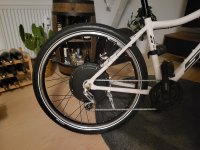
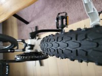
So I figured out that the hub motor I have is not a front hub, as I had ordered (I also ordered a 26" wheel, but it came on a 27.5" - which actually fits the bike better - I can't complain). It has threads on one side to fit a freewheel.
The hub motor axle width is also way too wide to fit inbetween 100mm MTB QR (quick release) front fork, which means that my plans for building a front hub is down the drain.
I will proceed with a rear hub build which is also not without it's challenges:

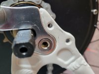
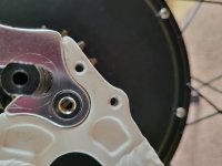
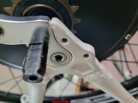
Uncentered rear hub

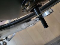
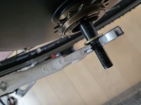
From the looks of it, my rear hub will not be centered in the frame, see pictures below:


As you can see from the last picture, there is no room to move the wheel more to the right, in order to center align the wheel.

What are the consequences of having an uncentered wheel? Is it viable to just ride like that?


Having to change to single speed gearing

Test fitting the rear hub leafmotor has made it evident that I will not be able to support the current gearing system. As there is not enough room between the frame and the hub motor(3.5 cm) to fit my 7 speed freewheel(4.1 cm):


I suppose I will try to figure out how to fit a single speed freewheel that will act as a high gear so that peddaling actually makes sense while using the throttle. I read a bit about gearing ratios, which is common knowledge for people running a mid drive I suppose. One other thing I have to figure out.


LewTwo said:
OOPS ... I missed that little detail. You might want to consider updating your profile to include locations information.
I added the location information, thank you :).
 
Note that the flat washers on each side need to be inside of the dropouts, not outside like in the pics. Also, to accommodate a 7 speed freewheel, you will often need 2 flat washers inside of the dropout on the freewheel side. While the measurements between the axle shoulders is 135mm, that doesn't include the required washers, so there's almost always some spreading of the rear dropouts in order to get the motor to fit.

If the wheel isn't centered after adding the washers, then re-dishing the wheel might be necessary. I switched to a 6 speed freewheel in order to eliminate the extra washer on the freewheel side, but looking at your pics, the extra washer may actually help to center the wheel.

I'm assuming you have the same issue at the seat stays.
 
E-HP said:
Note that the flat washers on each side need to be inside of the dropouts, not outside like in the pics. Also, to accommodate a 7 speed freewheel, you will often need 2 flat washers inside of the dropout on the freewheel side. While the measurements between the axle shoulders is 135mm, that doesn't include the required washers, so there's almost always some spreading of the rear dropouts in order to get the motor to fit.

If the wheel isn't centered after adding the washers, then re-dishing the wheel might be necessary. I switched to a 6 speed freewheel in order to eliminate the extra washer on the freewheel side, but looking at your pics, the extra washer may actually help to center the wheel.

I'm assuming you have the same issue at the seat stays.

Thank you - I've been off for a few days doing other stuff while waiting for parts to arrive.
I've fixed the washers and tried to align the wheel. It is now almost completely centered, as opposed to the earlier picture, but it is now scewed at the seat stay a little bit. Eventho it's a new bike, it's not straight in a lot of different areas like brakes and what not. I still need to install torque arms, which might aligment even better at the chain stay.

Rear-hub fit:

I've also managed to aquire a freewheel and have it installed now:
20221106_001814.jpg

Battery planning:
The rear rack and battery casing arrived a few days ago, so I've begun battery planning.
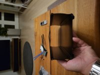
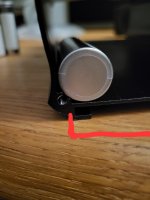
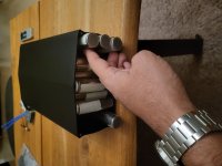
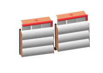
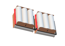
At first sight, it seemed like a 14S5P wouldn't fit, as I need a little bit of headroom for welding strips, wiring and a BMS. Not even a 13S6P (as the seller told me) would fit, because the battery housing has a shape that makes the middle taller and the sides shorter. The diagram from the seller shows measurements from the tallest part of the housing, which was a bit misleading.

20221106_000902.jpg

20221106_000914.jpg

The inside housing width from the point of the red line to the other side is 13.5 cm:

20221106_012245.jpg

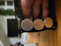
Having 6 cells on a row would not fit because of the lower sides of the housing. A row of 5 cells (10.5 cm) fits and leaves a gap of 1.5 cm on either side:

20221106_001015.jpg

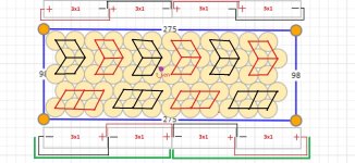
If I do a honeycomb layout for the cells, the width of 5 cells is about 9.6 cm. This will also enable me to have 12 cells on either side of the honeycomb pack, altho those cells will have a different orientation, but it will give me more headroom for the BMS, and make my wet dream of a 14S6P pack seem plausible!

This is the idea - having 5 columbs of 12 cells in the middle (26 cm length) and 4x3 packs (two P-groups) of cells on either side (28 cm length) - the housing is 29.5 cm and has probably 0.5 cm more to give from the junctions to the other housing elements:

20221106_001109.jpg

20221106_014037.jpg

Battery pack planning.jpg
I found a russian website with an online tool for planning your battery. If you are interrested, you can find it here: https://e4bike.ru/page/battery-shape-configurator?lang=en

Not exactly sure what the best practice would be of wiring up the P-groups on the sides to series in the pack - input is much welcome.

My own thoughts: Use copper-sheet tabs from honeycomb pack and connect by soldering with copper wire.
There might be more resistance in these connections, but they are placed in the outward part of the battery housing and will receive more cooling.

I'm not sure if the battery positive and negative should be made such that the P groups on the sides provide them either or if it would be better to have them placed on the honeycomb part of the pack.

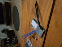
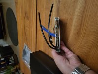
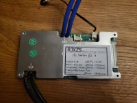
My 14S BMS only has a C- and a B- and two wires out from each:

20221106_001237.jpg

20221106_001306.jpg

20221106_001317.jpg

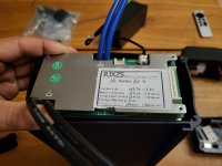
It's also a very snug fit in the battery housing:

20221106_002309.jpg

I'm not sure why there are two wires comming out of C- and B- on BMS - maybe it's because it's rated for 60A?
I've never seen a BMS with just C- and B- in my research. I take it that I have to wire up C- as one would do with P-(?). Wiring C- to Charge negative and Controller negative?

It also seems like I can discharge and charge through the same port which I find conveniant as the battery housing slides into rear rack by an Anderson connector (rated 50A), and I won't have to wire up the RCA charge port (which is rated to 5A according to the seller) - I could make a charger with an Anderson connector!:

20221106_001543.jpg

20221106_001613.jpg

20221106_001415.jpg


I'm sure there are upsides and downsides to charge and discharge from the same port, but I can't tell the downsides. Is there anything I should me mindful of in this regard? I'm worried if some sort of proctection is neglected.

Wiring of other components:

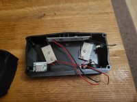
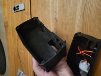
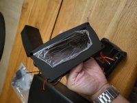
There are also wires comming out of the back part of the housing for rear lights and a button activated charge level display (also see 3rd picture up):

20221106_001533.jpg

I won't wire up the charge level display/button, as I have Bluetooth in the BMS to show voltage/charge. But the rear lights? There were no other electronics in the package of the rear rack and battery housing. I'm certain I can't just wire rear light diodes to my battery positive and negative (58v).

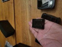
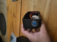
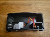
There is also a key lock fob in the front end of the battery housing with wires attached:

20221106_001339.jpg

20221106_001354.jpg

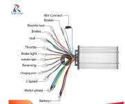
Is this supposed to be wired directly to the controller? - The wires just seem to thick, compared to the electronic lock wires comming out of the KT controller:

KT Controller.jpg

Pheeew... so many questions and uncertainties! I need to do more research - I hope, as I am documenting this build, the problems and questions encountered along the way will help other first time builders to achieve success! :bigthumb:
 
Sajeel said:
I've fixed the washers and tried to align the wheel. It is now almost completely centered, as opposed to the earlier picture, but it is now scewed at the seat stay a little bit. Eventho it's a new bike, it's not straight in a lot of different areas like brakes and what not.

If it's centered at the chainstays, but skewed at the seatstays, then it could be that the axle is sitting lower in one of the dropouts versus the other. Also, you may want to deepen your dropouts a couple of mm anyway, since the hub motor axle has a greater diameter than the bicycle wheel axle.
 
Sajeel said:
There is also a key lock fob in the front end of the battery housing with wires attached:

20221106_001339.jpg

20221106_001354.jpg

Is this supposed to be wired directly to the controller? - The wires just seem to thick, compared to the electronic lock wires comming out of the KT controller:

Yes, connect to the wires described as "Electrle lock" in your wiring diagram. Who knows why they chose thicker wires on the key lock.

Looks like your chain is a little short:
file.php


Ideally you want more chainwrap around the cog than that. Potential problem if you were to pedal vigorously-- chain skip is where the chain rides up over the tops of the sprocket teeth.
 
E-HP said:
If it's centered at the chainstays, but skewed at the seatstays, then it could be that the axle is sitting lower in one of the dropouts versus the other. Also, you may want to deepen your dropouts a couple of mm anyway, since the hub motor axle has a greater diameter than the bicycle wheel axle.

I didn't think that could be the cause of the skewedness - I was planning to file the dropouts down (being careful not to overdo it), once I install the torque arms. Should I file to widen the drop out, or file the "bottom" of the drop out?


99t4 said:
Yes, connect to the wires described as "Electrle lock" in your wiring diagram. Who knows why they chose thicker wires on the key lock.

Looks like your chain is a little short:
file.php


Ideally you want more chainwrap around the cog than that. Potential problem if you were to pedal vigorously-- chain skip is where the chain rides up over the tops of the sprocket teeth.

Thank you for clarifying with the "Electrle lock" - much appreciated!

I won't be pedaling hard or anything like that. The chain isen't mounted straight either, and will wear quicker because of that. Something I will fix down the line. I intend to use the throttle more than the pedals.. atleast for now. Thank you for also pointing out this issue!
 
Sajeel said:
Should I file to widen the drop out, or file the "bottom" of the drop out?
The goal is to get the center of the axle into the same spot that the bicycle wheel axle would be in.

If the original axle is, for example, 10mm, and seats fully into the dropout, then it's center is 5mm below the curve of the top of the dropout.

If the motor axle is, for example, 12mm, then to make it fully seat into the dropout and be at the same spot as the original, you'd need to carefully file 1mm out of the entire arc of the top of the dropout so it is still the same shape as the motor axle's threaded area, just 1mm deeper.


You don't want to widen the dropout, as there is no normal reason to do so, and a number of reasons not to. (if the motor axle wouldn't fit into the dropout at all because it's flatted sides were too wide to do so, that would be different, but that would be unusual to have happen).
 
Axle_Depth_in_Dropout_Slot.jpg


The example to the right is likely what you have. You can see that you need to reprofile the dropout slightly, since it's not only the depth, but the curve, to match the curve and the axle flats.
 

Attachments

  • Axle_Depth_in_Dropout_Slot[1].jpg
    Axle_Depth_in_Dropout_Slot[1].jpg
    25 KB · Views: 470
amberwolf said:
The goal is to get the center of the axle into the same spot that the bicycle wheel axle would be in.


E-HP said:
Axle_Depth_in_Dropout_Slot.jpg


The example to the right is likely what you have. You can see that you need to reprofile the dropout slightly, since it's not only the depth, but the curve, to match the curve and the axle flats.

Thanks to both of you! - I'll buy you a beer if you ever visit Copenhagen :D.

Filing the dropout down to fit the motor axle:

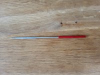
My wheel is now completely centered, after filing the dropouts down with a small rounded diamond file:

20221107_121206.jpg

20221107_121111.jpg

Before:

20221107_105518.jpg

After:

20221107_121152.jpg

20221107_125032.jpg

If I turn the wheel (with no bolts or screws attachted) there is a little bit of sideways "give" from the motor axle:

20221107_121521.jpg

20221107_121526.jpg

It's hard to tell, but you can see the side of the axle on one picture.
If I pressure the wheel into the dropouts while turning the wheel (to simulate weight while riding), there is no visible "give". Should I be worried about this and do something about it?

Thanks!
 
The torque arms are intended to do that job, if you mean to prevent the axle itself from rotating. Your bike's dropouts are not designed to resist the axle torque (there isn't any from a normal bicycle wheel, unless you have a drum brake or IGH), and many of them simply can't do it, whcih is why a good pair of torque arms is recommended. :)

It's even worse when you use a DD hubmotor and regen braking, because then it not only tries to twist the axle backward to drive the wheel forward, it then twists it the other way every time you brake, and back and forth eventually causes mechanical failures.

The teensy tiny surface area between axle flats and either dropouts or torque arms are the only way for the motor torque to be transferred to the frame so that the motor can spin the wheel and push the bike along. So there is a LOT of force at those spots, which can easily carve out metal and let the axle spin instead of the motor, which will rip out your wiring and often blow up your controller (and sometimes the motor halls).

As a recent example, these are pics of my SB Cruiser's heavy-duty dropouts, which are actually clamping on one end of the axle, and thick hard steel on the other--they survived bigger cheaper motors than what's on there now, but the even harder axle steel of the UltraMotors I've been using for a while now finally chewed thru the steel, actually carving threads into it. I ended up building new better clamping dropouts on both sides of the wheel and it's good so far....but I still check it every ride. ;) Note in the post-failure pre-fix images, the "keyhole" shape of the dropout is solely from the damage done; the dropout should be just like a regular one, flat on the sides and simple arch at the top. The rounded area is where the axle carved all that metal away as it spun.
https://endless-sphere.com/forums/viewtopic.php?f=2&t=67833&p=1737527&hilit=dropout#p1737527
file.php


file.php


file.php


file.php


file.php


file.php
 
amberwolf said:
As a recent example, these are pics of my SB Cruiser's heavy-duty dropouts, which are actually clamping on one end of the axle, and thick hard steel on the other--they survived bigger cheaper motors than what's on there now, but the even harder axle steel of the UltraMotors I've been using for a while now finally chewed thru the steel, actually carving threads into it.

That looks scary!

Torque arm fitting:
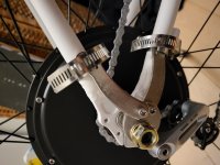
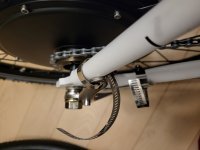
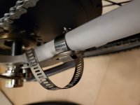
I couldn't fit my torque arms to rest on the stay, because of the design of the bike. I don't have machines to make my own torque arm either. I put on two torque arms on the side of the hub that I was able to, mounting them with a gardening hoseclamp to the side of the stays while having a mental note about torque forces going the opposite way of the forward turn motion of the wheel:

20221107_191017.jpg

20221107_191037.jpg

20221107_191042.jpg
 
If my trike didn't sit down on top of the axle allowing it no way to come out, it would've been scary--on a regular bike like yours it *is* possible for the wheel to come out of the dropouts after it breaks them off, and leave you scraping the road....

Trust me, you want both the arms on there, one on each side of the bike. Two clamp arms on the one torque arm on just one side is a lot less effective than two torque arms one on each side, each with their own clamp arm. There are better torque arms out there, like the Grin V4, rather than the (probably counterfeit) V1(?) those appear to be, but almost any arm is likely better than none.
https://ebikes.ca/product-info/grin-products/torque-arms.html#GrinTechTorqueArmDesigns
The idea is that the arm must fit tightly against the entire axle flat area, on both sides of the axle, or else it'll be able to rock back and forth, and could chew thru the torque arms, then the dropouts. :(

If you have both torque arms on the one side of the bike, that's better than only one, but it means the other axle end is still free to twist around in your dropout and damage it, and it's possible for some of these cheap-metal axles to actually snap on the end that *is* secured because of the back-and-forth wiggle that the unsecured end can have. It might not happen...but it has happened before.

I also don't recommend the stack of washers under the arms, but rather just one between the nut and the arms (to give a surface for the nut to rotate against), and the arm against the face of the dropout directly.

The nut needs to engage the axle threads fully, so that, if possible, it actually has some axle sticking out of it's end (because the end threads are incomplete and provide less grip). Otherwise it can't put the same pressure against the dropout plate (via the washer/arm plate) to keep it tightened, and keep the rest of the axle hardware secure (which is what it is there for).

I can't see if you also have a tabbed washer, but if you do, I would put that on the inboard side of the dropouts as a spacer between the axle shoulder and the dropout plate face, with teh tab down at the bottom end of the dropout. (if it's at the top end, it defeats the dropout filing you did to center the axle back in the dropouts, and filing too far into the dropout can weaken it, so you may not want to file further in to fit the tab at the top above the axle, especially since it does little to resist torque compared to the torque arm***.

The best way to install the torque arm if you can't fit it fully flat against the stay is to flip it 180 degrees so the screw mounting hole/tab sticks out behind the dropout plate, and then the arm for the clamp up to the stay to clamp to the frame, or if there is a bolt hole the axle arm portion can line up with, you can use that instead of the clamping arm.


See The Torque Arm Picture Thread for a bunch of pics of how people have installed their arms (and some DIY versions).


*** even the good tabbed torque washers liek these that are not just soft stamped steel can't resist torque like a torque arm made for the purpose; this is one of the ones I had on that wheel....
file.php
 
Good work on the dropout filing! Good job, well done with the proper tool! :thumb:

Now about those TAs:
file.php


Two glaring problems with your TA implentation:

1. That style/quality of TA is poorly engineered, designed, with slack fit tolerances, made of inferior materials, and not thick enough. I guess it's more affordable, hence it popularity. It's a cheap knockoff of Grin Tech's original TorqArm_V1, which they discontinued in 2010 due to unsatisfactory performance. You want TorqArm_V4:
TrqRev4.jpg

https://ebikes.ca/product-info/grin-products/torque-arms.html

2. Stacking two of them on the same side leaves insufficient thread engagement on that side axle/locknut.
 
Sajeel said:
I couldn't fit my torque arms to rest on the stay, because of the design of the bike. I don't have machines to make my own torque arm either. I put on two torque arms on the side of the hub that I was able to, mounting them with a gardening hoseclamp to the side of the stays

It looks like you have extra washers on the outside of your dropout. The axle only looks long enough for the one washer inside the dropout, and one torque arm outside the dropout so you can get full engagement from the axle nut. I'd go with the Grin torque arm pictured, since those cheap ones won't do much to keep the axle from twisting.
 
amberwolf said:
Trust me, you want both the arms on there, one on each side of the bike. Two clamp arms on the one torque arm on just one side is a lot less effective than two torque arms one on each side, each with their own clamp arm. There are better torque arms out there, like the Grin V4, rather than the (probably counterfeit) V1(?) those appear to be, but almost any arm is likely better than none.
https://ebikes.ca/product-info/grin-products/torque-arms.html#GrinTechTorqueArmDesigns
The idea is that the arm must fit tightly against the entire axle flat area, on both sides of the axle, or else it'll be able to rock back and forth, and could chew thru the torque arms, then the dropouts. :(

If you have both torque arms on the one side of the bike, that's better than only one, but it means the other axle end is still free to twist around in your dropout and damage it, and it's possible for some of these cheap-metal axles to actually snap on the end that *is* secured because of the back-and-forth wiggle that the unsecured end can have. It might not happen...but it has happened before.

I also don't recommend the stack of washers under the arms, but rather just one between the nut and the arms (to give a surface for the nut to rotate against), and the arm against the face of the dropout directly.

The nut needs to engage the axle threads fully, so that, if possible, it actually has some axle sticking out of it's end (because the end threads are incomplete and provide less grip). Otherwise it can't put the same pressure against the dropout plate (via the washer/arm plate) to keep it tightened, and keep the rest of the axle hardware secure (which is what it is there for).

I can't see if you also have a tabbed washer, but if you do, I would put that on the inboard side of the dropouts as a spacer between the axle shoulder and the dropout plate face, with teh tab down at the bottom end of the dropout. (if it's at the top end, it defeats the dropout filing you did to center the axle back in the dropouts, and filing too far into the dropout can weaken it, so you may not want to file further in to fit the tab at the top above the axle, especially since it does little to resist torque compared to the torque arm***.

The best way to install the torque arm if you can't fit it fully flat against the stay is to flip it 180 degrees so the screw mounting hole/tab sticks out behind the dropout plate, and then the arm for the clamp up to the stay to clamp to the frame, or if there is a bolt hole the axle arm portion can line up with, you can use that instead of the clamping arm.


See The Torque Arm Picture Thread for a bunch of pics of how people have installed their arms (and some DIY versions).


*** even the good tabbed torque washers liek these that are not just soft stamped steel can't resist torque like a torque arm made for the purpose; this is one of the ones I had on that wheel....
file.php

Lots of good stuff here! Thanks!

Yes, I have a tabbed washer on the outside of either side, having the tab face inwards towards the motor to "hold the axle in place of the dropout". There were also C-washers in the torque arm kits I mounted which I used to get correct spacing for the first torque arm to fit properly. It wouldn'tbe flat to the washer/frame otherwise.


99t4 said:
Two glaring problems with your TA implentation:

1. That style/quality of TA is poorly engineered, designed, with slack fit tolerances, made of inferior materials, and not thick enough. I guess it's more affordable, hence it popularity. It's a cheap knockoff of Grin Tech's original TorqArm_V1, which they discontinued in 2010 due to unsatisfactory performance. You want TorqArm_V4.

2. Stacking two of them on the same side leaves insufficient thread engagement on that side axle/locknut.


E-HP said:
It looks like you have extra washers on the outside of your dropout. The axle only looks long enough for the one washer inside the dropout, and one torque arm outside the dropout so you can get full engagement from the axle nut. I'd go with the Grin torque arm pictured, since those cheap ones won't do much to keep the axle from twisting.

You all have me convinced! I ordered two GRIN v4. They cost me a couple of dollars short of 150 :!:.
The price for safety (and protecting the other investments). Shipping, customs and duties.

I'll probably start working on the battery pack, as I wait for delivery.

Thanks guys!

soaresdacosta said:
Nice build, enjoying seeing. Keep going. :D

I will keep you posted 😁.
 
Planning the battery pack for a 14S6P configuration:

So, the idea was to honeycomb 4 rows of 12 cells in the middle and also have 12 cells laying down on either side of the middel/honeycomb part of the battery pack (in order to fit enough cells for a 14S6P pack):

Battery Parallel-series.png

Battery Parallel-series2.png

Please excuse my paint skills :lol:.
The red and black tubes are supposed to represent AWG wire. The current plan is to pre-solder the wires to the copper tabs, and then spot weld the tabs on to the batteries using the sandwich method, to avoid heat exposure. Obviously it needs to be much, much tighter than depicted - it's only for illustrative purposses for the wiring. I'm aware that it's a bad idea to have the tabs exposed further out than the cells - again, the depiction is for illustative purposses :).

3 cells laying down would connect with 3 cells from the honeycomb part making a parallel group, which would connect to the next parallel group of the same configuration. After four parallel groups in this manner series connected, I would series connect to parallel groups in the honeycomb part, and 'snake' it back towards the end where I started, and then make another snake turn. I would end up in the diagonal opposite side of the battery with the battery positive there.

I'll add a more detailed illustration tomorrow. Editing this post.
 
Sajeel said:
I've had a 48v 1000W kit conversion kit laying around for 2 years (Aliexpress). I sold my car and now I'm looking to do my first eBike build!

Given this is your first build, I would caution that you may be over-reaching with how complicated you're making the battery build. Even after you figure out all this weird sideways parallel/series connections, you will still have to adequately protect (fish paper) and have space for balance leads and probably want some form of inner shell protection (fiberglass, neoprene, etc). It'll get crowded very quickly.

It may be worth considering a more guided solution. For example, a more pre-designed kit like this DP-7-21700 which you can pretty easily mount on to a rear rack. Makes a first build much easier as it comes with holders, proper spacing, all the nickel and a decent enough BMS as one whole package.

If nothing else, I'd sacrifice that bit of range from the extra parallel group to make the battery build significantly easier and better.
 
Back
Top