≤2000w 96V charger ~$5

Looking like we are almost there. Something in series using 48v DC should make it ok to charge 24s lipo at the end.
 
WARNING! in case you didn't know Electricity is dangerous! ... to placate the fear mongers ...

Ordered me up a couple mug heaters ...
12V 10A cup mug water heater

And I couldn't resist the 12V 150w ceramic heater.
If nothing else, I won't have to let my car warm up for 10 min before I can see out the windshield, this Winter.
12V 150w ceramic heater for 12.5A regulation - <$15
Due to the nature of ceramic heaters, increased voltage might actually reduce Amps!

Both should be designed for typical car voltages, so ≤15V should work just fine, lower and likely higher as well.

WARNING! in case you didn't know Electricity is dangerous! ... to placate the fear mongers ...
 
WARNING! in case you didn't know Electricity is dangerous! ... to placate the fear mongers ...

Current regulation Bonanza!

Reprap 12v 40W Ceramic Cartridge Wire Heater - $1.58 each
12V 3.33A per item
Can be run serial or parallel

$T2eC16h,!wsE9suw0P0CBSGzTdZgRw~~60_12.JPG


Reprap 24v 40W Ceramic Cartridge Wire Heater- $1.58 each
24V 1.66A per item
Can be run serial or parallel

Ceramic heaters auto regulate temperature
( CAUTION! - but very hot! near 200ºC = 392ºF)
Amperage will be further limited as heat rises
Attaching to heatsink - fan will help maintain full rated amps ...
In water? ... not sure if submersible ...

I make reasonable effective heatsinks using aluminum tape
Taped to bike frame might disperse heat nicely?

WARNING! in case you didn't know Electricity is dangerous! ... to placate the fear mongers ...
 
WARNING! in case you didn't know Electricity is dangerous! ... to placate the fear mongers ...

riba2233 said:
If you waste that much energy on charging, what's the point of going electric?
40w heat to supply nearly 400w of charge is ~90% efficient.
Better than most chargers!

Penny for penny, electric vs gasoline, I get 1500-2500 eMPG.
Even at 50% charging efficiency ... electric looks a bit better ... ?

WARNING! in case you didn't know Electricity is dangerous! ... to placate the fear mongers ...
 
riba2233 said:
If you waste that much energy on charging, what's the point of going electric?
now that you discovered the harsh reality, (that your charger is wasting energy)
what will you do now? WALK :roll:
 
has anyone ever tried a single diode for half wave charging? that will cut the voltage in half i expect.
i have a 40 amp 600 PIV rectifier and a large heat sink.
 
DrkAngel said:
40w heat to supply nearly 400w of charge is ~90% efficient.
Better than most chargers!

Penny for penny, electric vs gasoline, I get 1500-2500 eMPG.
Even at 50% charging efficiency ... electric looks a bit better ... ?

In that case - 8)

But in Europe we have 230 V in our walls, so your method couldn't work without wasting too much energy.
 
WARNING! in case you didn't know Electricity is dangerous! ... to placate the fear mongers ...

riba2233 said:
DrkAngel said:
40w heat to supply nearly 400w of charge is ~90% efficient.
Better than most chargers!

Penny for penny, electric vs gasoline, I get 1500-2500 eMPG.
Even at 50% charging efficiency ... electric looks a bit better ... ?

In that case - 8)

But in Europe we have 230 V in our walls, so your method couldn't work without wasting too much energy.
For you. ... ?
Fortunately ... there are many many others who might be able to benefit.

WARNING! in case you didn't know Electricity is dangerous! ... to placate the fear mongers ...
 
WARNING! in case you didn't know Electricity is dangerous! ... to placate the fear mongers ...

Most promising for my usage:
44.4V dual pack rigged in series 88.8V (3.7V) + 12V 10A (≥15V13A?) cup heater = 100V DC empty
44.4V dual pack rigged in series 99.6 (4.15V) + 12V 10A (≤10V8A?) cup heater = 110V DC full

The question is at what voltage the 120V AC >> 110V DC will stabilize?
(AC "wave" peaks at 164V DC through the circuit. (from my 120V AC and the 30A bridge rectifier I used))

My AC >>> rectified DC experience is with running leds in series.
Running this bridge rectified 110V DC through 3 - 32-35V 30w 900mAh leds (+ 10w 10ohm resister) in series gets me a 110V DC metered reading.
AC meter reads 120V ~100w <1A so, through this circuit, 110V DC is supplied, (not the warned against 164V DC).
Of course this is "rough DC".
Likely pulsing between 60-160V ...
AC rectifiedjpg.jpg


Charging a battery, where amperage and usage steadily declines, might be very different.
I guess it will be necessary to build a 26s, (or 24s w/12V heater = preferred), battery pack to actually determine-confirm tho ...

WARNING! in case you didn't know Electricity is dangerous! ... to placate the fear mongers ...
 
always use a timer with an unregulated charger
https://www.surpluscenter.com/Electrical/Meters-Counters-Timers/Timers/60-MINUTE-115-VAC-MOTORIZED-TIMER-11-3324.axd
 
riba2233 said:
DrkAngel said:
40w heat to supply nearly 400w of charge is ~90% efficient.
Better than most chargers!

Penny for penny, electric vs gasoline, I get 1500-2500 eMPG.
Even at 50% charging efficiency ... electric looks a bit better ... ?

In that case - 8)

But in Europe we have 230 V in our walls, so your method couldn't work without wasting too much energy.

Its possible.
2x 25s (96V controller) or 3x 17s (72V controller) would fit to 209V DC rectified.
But would be inconvenient to always unplug from controller and than serial/parallel the batteries.
 
WARNING! in case you didn't know Electricity is dangerous! ... to placate the fear mongers ...

Even 110V DC can be lethal!
Multiple sources mark ~50V DC as the transition point of possible lethality ... so treat electricity with respect.

There is available a simple inexpensive way to switch battery packs from parallel to serial ...

DrkAngel said:
Re-rigged a Forward reverse switch as a 24V to 48V shifter.
2 - 24V packs, "shifted" from parallel to serial. *
Switch does disengage all power in "neutral" center position.

Serial - Parallel Schematic
file.php


Available at - EBike Toolbox - Bargains! $

* Important to remove bus bar on left side between #2 and #5 for Serial Parallel
Forward - Reverse Schematic
file.php


WARNING! in case you didn't know Electricity is dangerous! ... to placate the fear mongers ...
 
if you want to try 24s, no need to wait for that 12v heater, it will likely burn up anyway.
hook the 24s in series with a blow drier or 120v heater, just to check amps, for a quick test, a classroom experiment, not the final solution, ...
just for fun, i plugged in a bridge w/68uf cap. and got 170vdc
also a 15vac wall wart, w/bridge got 15vdc, and with the cap, 22.8vdc. so can you charge 5s2p with it? anyone not know the answer?
.
so one could use a HALF WAVE, not a bridge, to charge 20s, or 10s with a switch, this works out to no load average of 4.25v per cell, and it would only get this high if one was too lazy to use a timer, and fell asleep!
 
Clearly, some sort of PWM control is needed so a variety of voltages could be charged.
http://www.ebay.com/itm/Universal-DC6-90V-15A-PWM-HHO-RC-Motor-Speed-Controller-Module-Switch-Work-Well-/331315679429?pt=LH_DefaultDomain_0&hash=item4d23f410c5
this takes up to 90vdc and is only $7 and 10-15 amps!
so i propose using HALF WAVE from house ac for a max of 85vdc no load, and just turn the knob for your needed voltage, 12v to about 72v.
I have one and have tested it even at 20 amps on my scooter, for brief acceleration, and it works, but does not have constant current, so be careful! Don't want your battery trying to do a wheelie :shock:
.
and i just ordered:
http://www.ebay.com/itm/2000W-SCR-Voltage-Regulator-Dimmer-Speed-Temperature-Controller-AC-110-220V/201071530709?_trksid=p2047675.c100010.m2109&_trkparms=aid%3D555012%26algo%3DPW.MBE%26ao%3D1%26asc%3D25880%26meid%3D1c2cf9b23c9044f9bff83337d6939d53%26pid%3D100010%26prg%3D10819%26rk%3D3%26rkt%3D24%26sd%3D221464802245
 
Matt Gruber said:
just ordered:
http://www.ebay.com/itm/2000W-SCR-Voltage-Regulator-Dimmer-Speed-Temperature-Controller-AC-110-220V/201071530709?_trksid=p2047675.c100010.m2109&_trkparms=aid%3D555012%26algo%3DPW.MBE%26ao%3D1%26asc%3D25880%26meid%3D1c2cf9b23c9044f9bff83337d6939d53%26pid%3D100010%26prg%3D10819%26rk%3D3%26rkt%3D24%26sd%3D221464802245
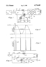
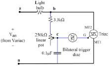
An SCR like that or a Triac circuit is easier way of full wave dimming the d.c. load through the bridge rec, the power factor could be a lot better too, so the full value of real power could be used instead of 1kW, 2 or 3kW might be available from the same outlet
US4774449-1.png
images.jpeg
A few modern additions like circuit breaker for close protection, MOV and filter on mains side and tvs or zener on dc side maybe, might be able to tame a bad boy :mrgreen: without a whopping big wastey series load.
 
DrkAngel said:
Re-rigged a Forward reverse switch as a 24V to 48V shifter.
2 - 24V packs, "shifted" from parallel to serial. *
Switch does disengage all power in "neutral" center position.
Serial - Parallel Schematic
file.php
[/quote]
Is that current rating continuous or switching rating?
 
WARNING! in case you didn't know Electricity is dangerous! ... to placate the fear mongers ...

megacycle said:
DrkAngel said:
Re-rigged a Forward reverse switch as a 24V to 48V shifter.
2 - 24V packs, "shifted" from parallel to serial. *
Switch does disengage all power in "neutral" center position.

* Important to remove bus bar on left side between #2 and #5 for Serial Parallel
Serial - Parallel Schematic
file.php
Is that current rating continuous or switching rating?

Switch is 60A.
Picture-schematic illustrates 2 variations of same cells.

WARNING! in case you didn't know Electricity is dangerous! ... to placate the fear mongers ...
 
so i'm doing a little test,
i plugged a 15v 2.4a wall wart into a lamp dimmer
with just ONE 18650, 1/10 the pack size at 1/10 the volts
just turn the knob to set the amps,
tried 2.4a, then set it back to 1a, now .5a
easy to use, just wanted to see that it works.
went from 3.92v to 4.09 in about 15 minutes.
.
i have some caps from an old HVAC, but i don't have a big pack to charge, so no BAD BOY for me.
 
Safety is an important requirement for any charger, regardless of the cost.

The advantage of a series capacitor is that it limits current without dissipating (much) power. A series fuse can provide good protection for a short, while an open is inherently safe.

Resistors such as heaters in series will dissipate significant power. Not a good choice.

Line voltage is not constant, it varies over time and with location. A charger must adapt to this changing voltage. A bridge alone cannot and will fail to produce a stable charging current.

Reliable and safe end of charge detection and auto shutoff should be part of any charger, making the $5 inadequate.

Direct to line charging is quite dangerous, take extra care in your experiments. Insure that nothing with voltage can be touched, and that fire in the battery pack will not be a problem.
 
The original bad-boy charger thread shows you how to make one that is both much more efficient, more compact, and doesn't require a fan cooling power resistors because it uses a motor-start capacitor to limit the incoming AC current (and hence outgoing DC current) uniformly across a wide output voltage range.

I admire the confidence and get-it-done attitude of DrkAngel. However, he has some delusions about the way this circuit and current flow in an AC circuit behaves.

First, lets explore how to limit current. When a capacitor is in series with an AC source, it can only transfer as much current as it stores on each wave of voltage fluctuation. This makes your current limited by frequency, how handy because this stays constant inside 0.1% typically. You can adjust the amount of charge current by adjusting the value of the cap.

Neither this method or the resistor method stops charge current from just creeping up towards ~156vdc. It matters not if you have a cap on the output, as the cells themselves function as a massive capacitor bank, as cells are also capacitors simultaneously.

If the cap you choose for input current limiting isn't designed as a continuous-run motor cap, it will boil it's guts out, yet most still survive for a few minutes at least.

This method doesn't require arrays of heating elements, therefore doesn't need a bunch of fans or water to boil or whatever to operate continuously. If you get the wrong type of cap, it will overheat and boil it's electrolyte out and often short making a cool show, so don't get the wrong type of cap if you don't wish to have that experience.
 
WARNING! in case you didn't know Electricity is dangerous! ... to placate the fear mongers ...

AC cap on the AC side for current limiting.

Extrapolating from:
220V AC
"40uF = 2.5A "
"80 MFD 440V that cost $16. Puts out 3A continuous at 120V."
"70-82 mfd = 4.6a"
"250uF = 15A"
>325V capable required for 220V!

Then:
10uF = .625A
20uF = 1.25A
30uF = 1.875A
40uF = 2.5A
50uF = 3A
100uF = 6A
150uF = 9A
200uF = 12A
250uF = 15A
300uF = 18A

Same amperages from 110-120V AC?
Not sure if 110V is directly translatable?
>160V caps! ... ?

WARNING! in case you didn't know Electricity is dangerous! ... to placate the fear mongers ...
 
This is the type of cap that survives continuous 60hz charge/discharge duty:

http://www.surpluscenter.com/Electrical/Capacitors/Motor-Run-Capacitors/6-MFD-370-VAC-RUN-CAPACITOR-22-1103.axd


I realize it says only 6uF, and I think that may only get you 4A charging (60charge cycles with energy transferred, and 60discharge cycles with energy transferred) or whatever, so you would need something like 4 of them to get 16A charging.

As an alternative, one could try using some higher energy storage density caps to make tiny compact systems, but it would take some experimentation to find the right cap choice. Perhaps some of the heavy foil poly-caps

http://www.ebay.com/itm/Lot-of-100-Capacitors-0-56uF-630v-film-Tesla-coil-/151410840311?pt=LH_DefaultDomain_0&hash=item2340ca12f7

This cap is an extremely well proven robust cap for Tesla coils (I've never tried in in an AC circuit as a current limiter, but from reading it's datasheet, I saw no reason it wouldn't work.) It appears to be capable of passing 3A RMS each, and since each cap is only 0.56uF, at our low 60hz frequency each cap will only be contributing something like 0.4A charge current. However, I could easily see a 5x5 grid of this cap being constructed that will wouldn't take up much space, only weigh a pound or two, and make someone a very compact ~10A charger able to do both low voltage and high voltage packs alike.

If you care enough, order some sample caps of stuff that says it has low ESR and high continuous RMS ripple current ratings (and make sure it's a bipolar/unipolar cap!) and do some testing. :) In my build, I used a high current capable lightbulb in series with my output to further cushion the duty on the cap, which helped it run a bit cooler at the cost of some efficiency in burning some of that energy in the filament. If you tune the size of cap to your individual charging needs though, that shouldn't be needed, I was just making due with the cap I had laying around.
 
Back
Top