
I don't know monster. I might get some beads and try some more filters but If that doesn't work I would say that I should have went "analog." I'm not sure how much "needle bounce" you get on those type of gauges when going down the road from vibration and bumps though. A few members run them so I'd imagine they work ok.
You are using an out of date browser. It may not display this or other websites correctly.
You should upgrade or use an alternative browser.
You should upgrade or use an alternative browser.
.
- Thread starter D-Man
- Start date
monster said:so let me get this straight...
if you have a brussless motor a DC volt meter wont alow you to see real time voltage because it comes in pulses. -what about an AC volt meter?
what about current reading using a DC meter and shunt, thats the same problem i suppose?
i've just ordered a shunt and amp meter thinking it would all be simple to wire up. wish i'd read this post first!
If you want to measure the battery voltage, it doesn't matter what kind of motor you're running. Likewise if you want to measure the battery current.
It gets screwed up if you want to measure the motor current or voltage in a brushless system. I don't know anybody who's doing this except Patrick, when he was testing the Mars motor.
You will get some noise on the battery wires in either a brushed or brushless system that can interfere with a digital meter. Filtering can resolve this. An analog meter filters mechanically. I have an analog ammeter on my Vego, and I don't really have much trouble with bounce. The pointer needle is counterbalanced, so vibration does not affect it too much.
Drunkskunk
100 GW
D-Man said:Looks like the voltmeter gauge is having some problems still. It works fine at full throttle but at part throttle (not accelerating) it reads lower then at full throttle. I checked with a fluke meter. I'd imagine its probably more noise coming in on the imput side. One other thing, I noticed that when I read the boost battery, its voltage will drop a few tenth's even when I'm not using it. (under acceleration) I guess this cheap gauge is for people who like to experiment.
That doesn't sound like a meter problem. its pulsed DC. essentualy, its AC voltage at high frequancy. You would need an Oscope to read it properly.
On a brushless motor, the motor is getting full voltage all the time, but the pulse width is being modulated, With narrower bands for slower speeds. If your digital meter's sampling rate isn't the same as the controler's (And it won't be) then you can get some weird readings because of the apparent harmonics caused by the hit and miss nature of measuring pulses without being synced to them.
You could put a capacitor across the meter side to filter it even more. Interesting that the chokes help that much.
monster said:so are you saying fechter that if i put the meters between battery and controler then online measurements will be ok? its only the motor side which has the problem.
thats good
Right. That's how most people setup their meters, between the battery and the controller. The controller capacitors smooth out the power fairly well so not too much noise gets into the battery wires. It also doesn't make any difference what kind of motor you're using.
Doctorbass
100 GW
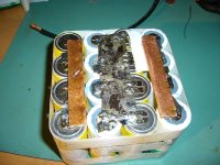
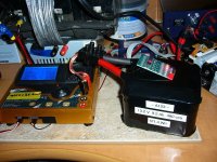
Here is my Boost pack... I finished it tonight.
I'm using 16 A123 4s4p to get 13.2V 9.2Ah 480A peak.
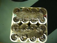
I used pure cooper bus bar of 17000 square mils and 4 gauge wire for the connector to allow more current.. like for car audio appications.
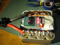
I put a plug for a blinky balancer too to keep the cells in good health
I got 64kph and acceleration power peak of 3250W at 86V.
Here are some pics of it:
Doc
I'm using 16 A123 4s4p to get 13.2V 9.2Ah 480A peak.
I used pure cooper bus bar of 17000 square mils and 4 gauge wire for the connector to allow more current.. like for car audio appications.
I put a plug for a blinky balancer too to keep the cells in good health
I got 64kph and acceleration power peak of 3250W at 86V.
Here are some pics of it:
Doc
Attachments
vanilla ice
1 MW
Nice!
TylerDurden
100 GW
I like it Doc!
May I suggest: fill the spaces between the cells with "great stuff" spray foam. Cylinders side by side (not nested) will try to shift and put torque on the connections. Filling the spaces will stop the tendency to shift.

May I suggest: fill the spaces between the cells with "great stuff" spray foam. Cylinders side by side (not nested) will try to shift and put torque on the connections. Filling the spaces will stop the tendency to shift.
xyster
10 MW
Nices hoses (wires), they look like veins and arteries. Cool. ")
Not much copper resistance there!
How does that balancer thingy work? What model is that?
How does that balancer thingy work? What model is that?
Similar threads
- Replies
- 7
- Views
- 221
- Replies
- 3
- Views
- 136
- Replies
- 6
- Views
- 267
- Replies
- 4
- Views
- 201
- Replies
- 0
- Views
- 140