Unless it has software to program it, you can't set anything (including regen charge voltage). Most of the controllers with jumpers don't have any non-factory setup software (most don't even have displays with settings the user can change, or assist levels, etc...because if they did they wouldn't need the jumpers and hardware costs money).
Those jumpers are for the controller base-voltage, which usually affects the regen voltage in those controllers that do regen and are designed for doing that, but how they affect it you would have to experimentally determine.
The controller base voltage determines the expected full-charge HVC and empty LVC voltages of the pack type labelled on the jumper (i.e. 48v = 52-54v HVC / 40-42v LVC, and determines the point at which the controller stops operating the motor (for accelleration or braking). You'd have to experimentally determine what this specific controller uses for LVC and HVC for any particular jumper, as even if it's the same "brand" as a documented one somewhere, unless it is identical hardware and firmware versions it may be different internal settings...and the factory "programming" may, even then, override anything.
If they're actually electrically connected to a phase wire, they are probably for a "scooter/motorcycle" speedometer that uses battery-voltage-level phase inputs from a hubmotor to calculate speed (these speedos must be programmed by the end-user with the right number of poles, wheel size, etc, for that to be useful--there's a thread about an APT version of one of these around here somewhere).
Don't connect them to anything unless you are *sure* that thing can take a minimum of full battery voltage (there can be peaks of much higher voltage during regen braking, too)
What specifically makes you think either of those? (just curious)
Unfortunately without a diagram there's no way for us to know for sure which wire is which on any random controller.
If you poke around, there are a number of threads (usually with "controller" in the title, sometimes also "wiring" or "wires") where people either were figuring out the wiring for a controller, or testing / reviewing it, or modding it, where some of the various pads on them may have been noted down for what their functions and markings were. No guarantee that any particular marking is the same on any two controllers (even from the same brand, or seller, etc--see the Greentime thread for some examples if hte pics are still there for them all), and almost certainly wire color isn't relevant, with the possible exception of black for ground and red for positive..but even there, red can be 5v *or* battery voltage, and connecting the one to the other usually makes for a very dead controller.

Even hall/phase wires may not be "standard"--I have one that's all green wires on all phase and all hall wires! (and it's only sensorless--it does not even try to use hall signals, at all, under any conditions, even though it has the wires).
One problem is that many of the "F1, 2, 3" or "A1, 2, 3", or "X1, 2, 3" type pins could have different functions depending on the firmware in the controller, and the only way to find out most of them is to try them out and see. Most of the input functions are activated by grounding the pin...but if it's an output grounding it could damage the MCU and kill the controller, so all experiments could leave you needing a new one. :/
Most non-programmable controllers that can do regen just have on/off regen at some preset amount, tied to the ebrake line. Some controllers have a high brake (12v or higher to engage, meant to connect to your brake light on scooter/MC) and a low brake (ground to engage), and most do the same thing no matter which one you use. A few only regen if one of them is used, and the other just turns off the motor. (which does what you'd have to experiment with, if you can experimentally determine which wire is which, or if it even has a brake wire).
If it doesn't have a display connector specifically, then it isn't going to work with a typical display.
If you have some other kind of display in mind, you'll have to link us to a webpage with the info on it, or post all the info you have about it if you already have one you're thinking of.
Without even knowing what brand/model controller it is, that's unlikely to be possible.
If you link to the place you bought it from, it might have info we can use to help you find more info.
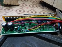
If you post a pic of the labelling on the controller casing, that might also lead to more info.
The more you tell us about it the more info we have to help you with.
No guarantees that more info will help, but the chances improve.
6/12 is just 60 or 120 degree hall spacing. Most likely you ground this wire for 60 degree halls, and leaving it unconnected gives you 120 (the most common).
XS...there's different uses for that abbreviation on different controllers; I don't know which one yours is.
...there's different uses for that abbreviation on different controllers; I don't know which one yours is.
Probably.
Could be--different controllers use different pins for the 3-speed switch.
Don't know; you'd have to test them...as noted, different controllers use various possible markings or pins....

 20240307_130909.jpg3.6 MB · Views: 11
 20240307_130951.jpg2.5 MB · Views: 13
 20240307_131007.jpg2.4 MB · Views: 12
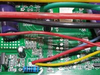 20240307_131033.jpg2.9 MB · Views: 11
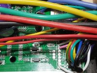 20240307_131045.jpg2.8 MB · Views: 10
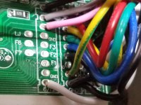 20240307_131100.jpg2.7 MB · Views: 13
 20240307_131121.jpg1.4 MB · Views: 11
 20240307_131125.jpg1.2 MB · Views: 12
 20240307_131158.jpg1.2 MB · Views: 12