8.4V Charger for a 2S Kweld

Darren2018

100 W
Joined
Aug 18, 2018
Messages
223
I am trying to finish my Kweld setup. At the moment I have 2x 2S 5Ah graphene packs paralleled together which do around 1175A when welding pure 0.15mm nickel which is perfect. What I would like to do is have a charger keeping them at 8.2V. I have bought a 8.4V charger and a simple BMS but there isn't a trim pot inside the charger. I can see a resistor but I am not sure if it's the correct one to trim the voltage. Could someone who knows about these things have a look and tell me what I need to do? I do not really want to leave the batteries at the chargers 8.44V because this will reduce the longevity of the cells and it also leaves little to no margin for imbalances over time. The BMS is the usual sort that is accurate to about 0.2V so not ideal for anything else other than a safety cut off switch.

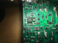
Here is the PCB

View attachment 1
 
i can't read the numbers on the two 8-pin chips on the bottom side of the board, but typically near the charger output there's a comparator. that's prbably the larger chip. you can look up the number on the chip to get it's specs and what pins do what.

it's going to have a voltage divider (two resistors, one to +v supply, one to ground, connected in the middle and to a pin on the comparator that's an input). that voltage divider is usually setup to cause the comparator to "switch off" at some specific voltage, which is the charge termination.

it's not really usually switching off at a voltage, but rather once charge current drops below some point, but that's still based on the voltage at this divider, so experimentation with the resistances in the divider will still usually change the termination voltage.


if you find the divider, you can replace both resistors with a single potentiometer that equals the value of the two resistors in series. adjust the pot before installation to match the resistances previously there (from center to each outer leg). then install with one outer leg of the pot goes to the point one resistor connects into the circuit, the center leg of the pot goes to where boht resistors connected together, and the other outer leg goes o the other resistor's connection point into the circuit.

then you can very very slowly adjust the pot while measuring the charger output voltage (not connected to the battery), until it reads what you want termination voltage to be.


or you can try figuring out enough of the circuit to be able to do math ratios on the resistances vs the voltages, and calculate what resitor you can parallel with one of the other two to get the output you watn.

or experimentally parallel a ptoentiometer across just one resistor and adjsut it until it gets what you want; if it doesn't then put it on the other resistor instead and try again.

etc.


keep in mind it's possible to let all the smoke out during any of these steps, so...while experimentation and diy can be fun, it can also be expensive. ;)
 
Or put an adjustable HVC in between, and tweak the cutoff voltage so that for that battery and that level of current you are just getting to the battery's OCV resting voltage that you desire.

Maybe something like
https://www.ebay.com/sch/i.html?_nkw=6-60V+Charging+Control+LCD+Protection
?
 
amberwolf said:
i can't read the numbers on the two 8-pin chips on the bottom side of the board, but typically near the charger output there's a comparator. that's prbably the larger chip. you can look up the number on the chip to get it's specs and what pins do what.

it's going to have a voltage divider (two resistors, one to +v supply, one to ground, connected in the middle and to a pin on the comparator that's an input). that voltage divider is usually setup to cause the comparator to "switch off" at some specific voltage, which is the charge termination.

it's not really usually switching off at a voltage, but rather once charge current drops below some point, but that's still based on the voltage at this divider, so experimentation with the resistances in the divider will still usually change the termination voltage.


if you find the divider, you can replace both resistors with a single potentiometer that equals the value of the two resistors in series. adjust the pot before installation to match the resistances previously there (from center to each outer leg). then install with one outer leg of the pot goes to the point one resistor connects into the circuit, the center leg of the pot goes to where boht resistors connected together, and the other outer leg goes o the other resistor's connection point into the circuit.

then you can very very slowly adjust the pot while measuring the charger output voltage (not connected to the battery), until it reads what you want termination voltage to be.


or you can try figuring out enough of the circuit to be able to do math ratios on the resistances vs the voltages, and calculate what resitor you can parallel with one of the other two to get the output you watn.

or experimentally parallel a ptoentiometer across just one resistor and adjsut it until it gets what you want; if it doesn't then put it on the other resistor instead and try again.

etc.


keep in mind it's possible to let all the smoke out during any of these steps, so...while experimentation and diy can be fun, it can also be expensive. ;)

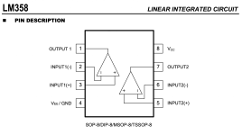
Thanks. I found this http://www.unisonic.com.tw/datasheet/LM358.pdf

Screen Shot 2020-01-24 at 04.37.19 am.png
IMG_4169.JPG

It looks like someone has changed the resistor that goes to pin 5?
 
Back
Top