Matador
100 kW
- Joined
- Jun 29, 2016
- Messages
- 1,045
Hey there. Quick question for you folks.
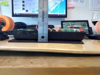
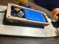
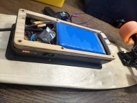
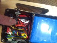
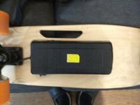
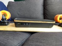
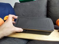
I have a cheap e-skateboard called the "Small Fish Plate" (mono hub motor 250W). It runs on a 7S1P Lithium cobalt oxide battery (cells are cheap chinese BFN 2000 mAh). The fun kicktail skateboard weights only 9 pounds, is easy to carry to work and tops out at 18 km/h. That's great for my 2.1 km commute to work in downtown Toronto. Charges from 30% to 100% in a hour or so... Here's a vid presenting the thing and it's guts: [youtube]GYS726Gx3fk[/youtube]
But no surprise here, the battery gave out after just one month (I expected that, but had some spare quality cells to use and rebuild...). So I rebuilt a battery. A more robust battery. The controller peaks at around 10A max. So that was a bit hard on that cheap chinese BFN 7S1P 2Ah battery (chinese cells each had around 52 mOhm DCIR, exept the one dead cell which was above 1000 mOhm DCIR). On the original battery, there is no real balancing BMS, just a protective 7S 15A-PCB (LVC and HVC cell monitoring).
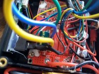
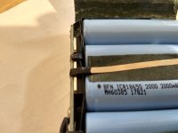
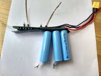
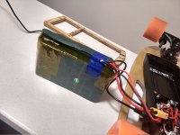
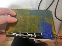
This was the old battery (7cells only ! Hard to believe it but while it worked, I onced did 4.8 km before it died...):View attachment 11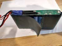
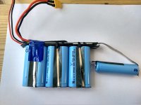
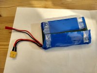
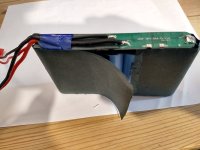
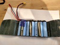
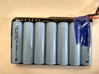
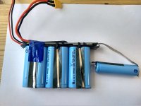
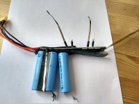
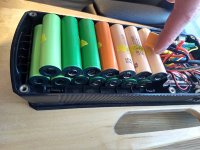
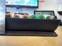
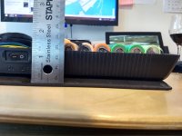
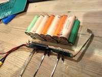
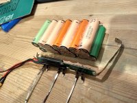
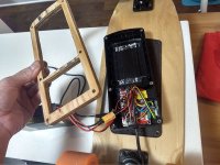
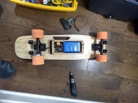
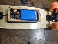
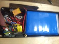
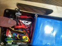
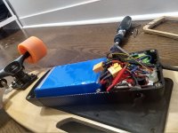
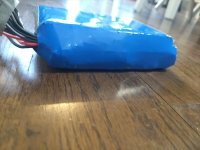
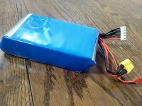
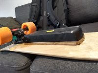
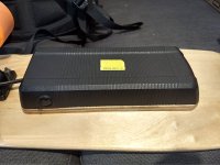
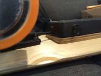
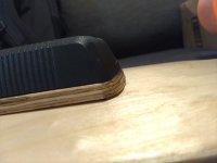
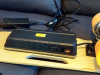
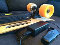
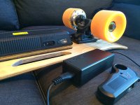
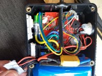
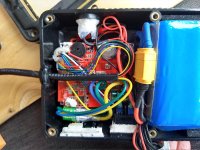
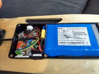
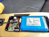
So I built a 7S2P battery from recycled dyson battery packs that had faulty BMS (one had 6 Sony VTC4 (2100 mAh NMC, max 30A, 23 mOhm), one had 6 Samsung HD2C (2100mAh NCM, max 22A, 22 mOhm), and also used two LG MH1 (2150mAh, LCO, max 10a, 42 mOhm). I transplanted the protective PCB on the new battery. Of course I balanced all cells to 0.01V before paralleling. Pictures: View attachment 8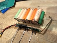 View attachment 6
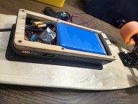
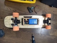
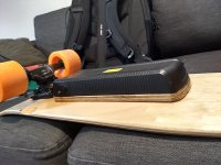

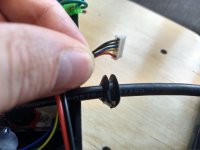
Even though there is a protective PCB, I did attach some manual balance leads with a JST connector to new bigger battery. Just to check cell voltage once in a while.
Well guess what. The original 7S 2A charger (I did not suspect) overcharged the battery to 29.65V (4.236V per cell) instead of stopping at 29.4V (4.20V)... I worried about poor cycle life...
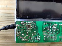
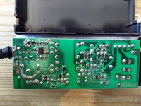
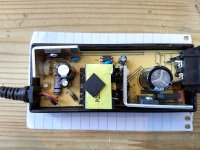
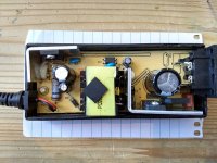
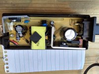
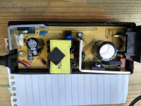
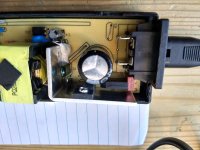
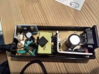
So I opened up the charger... But there is not trim pot at all in it. So I bought a Schottky diode. More specifically it's a 5A capable Vishnay IR 50SQ100 diode (datasheet: https://www.mouser.ca/datasheet/2/427/Vishay_50SQ060,080,100(M3)-1-1211393.pdf).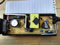
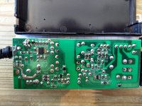
THE QUESTION:
Can I just connect the diode at the charger's output and hope it will reduce voltage (slight voltage drop) enough to bring cells below 4.20V fully charged ??? Charger output on full cells is currently 29.65V. I would like the charger to terminate at 29.40V and stop.
There are no trim pots inside. I assume the charger is the usual CC-CV type.... and probably stops charging when reaching below 100 mA charge current, not sure (the LED turns from green to red when charging process terminates). I did check the datasheet graph showing foward voltage drop versus current for the schottky diode.
For the diode, voltage drop at 25°C is -0.55V@2A, -0.39V@0.1A, and -0.37V@0.05A. At higher temperature 125°C that voltage drop is a bit less : -0.42V@2A; -0.24V@0.1A; 0.21V@0.05A.
Since this charger usually become hot to touch, I assume temps will be sort of in the middle between 25°C and 125°C. So I assumed an average at 75°C : voltage drop would be -0.48V@2A; -0.32V@0.1A; -0.29V@0.05A.
So based on this I would be good. If charger cuts out below 100 mAh, I should get 29.65-0.32V = 29.33V at the end. But I'm worried about something.
Will the charger not cut out in the end because the voltage output will be lower ? Will I destroy the battery cells in the end for some reason ? I'm not worried about imbalance since the PCB does not balance anyways.
Will the fact that at 2A (at the begenning of the process of recharging the battery) the diode will cause a -0.48V drop on the output cause unreasonnably longer charging times ???
I'm hoping somebody has some insight on this diode method. Maybe i should just leave it as is and charge to 4.24V (I can't constantly monitor voltage when charging at work...).
Thanks in advance!
Matador
I have a cheap e-skateboard called the "Small Fish Plate" (mono hub motor 250W). It runs on a 7S1P Lithium cobalt oxide battery (cells are cheap chinese BFN 2000 mAh). The fun kicktail skateboard weights only 9 pounds, is easy to carry to work and tops out at 18 km/h. That's great for my 2.1 km commute to work in downtown Toronto. Charges from 30% to 100% in a hour or so... Here's a vid presenting the thing and it's guts: [youtube]GYS726Gx3fk[/youtube]
But no surprise here, the battery gave out after just one month (I expected that, but had some spare quality cells to use and rebuild...). So I rebuilt a battery. A more robust battery. The controller peaks at around 10A max. So that was a bit hard on that cheap chinese BFN 7S1P 2Ah battery (chinese cells each had around 52 mOhm DCIR, exept the one dead cell which was above 1000 mOhm DCIR). On the original battery, there is no real balancing BMS, just a protective 7S 15A-PCB (LVC and HVC cell monitoring).
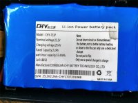
This was the old battery (7cells only ! Hard to believe it but while it worked, I onced did 4.8 km before it died...):View attachment 11


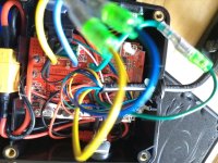
So I built a 7S2P battery from recycled dyson battery packs that had faulty BMS (one had 6 Sony VTC4 (2100 mAh NMC, max 30A, 23 mOhm), one had 6 Samsung HD2C (2100mAh NCM, max 22A, 22 mOhm), and also used two LG MH1 (2150mAh, LCO, max 10a, 42 mOhm). I transplanted the protective PCB on the new battery. Of course I balanced all cells to 0.01V before paralleling. Pictures: View attachment 8
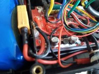
 View attachment 6


Even though there is a protective PCB, I did attach some manual balance leads with a JST connector to new bigger battery. Just to check cell voltage once in a while.
Well guess what. The original 7S 2A charger (I did not suspect) overcharged the battery to 29.65V (4.236V per cell) instead of stopping at 29.4V (4.20V)... I worried about poor cycle life...
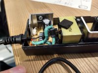
So I opened up the charger... But there is not trim pot at all in it. So I bought a Schottky diode. More specifically it's a 5A capable Vishnay IR 50SQ100 diode (datasheet: https://www.mouser.ca/datasheet/2/427/Vishay_50SQ060,080,100(M3)-1-1211393.pdf).


THE QUESTION:
Can I just connect the diode at the charger's output and hope it will reduce voltage (slight voltage drop) enough to bring cells below 4.20V fully charged ??? Charger output on full cells is currently 29.65V. I would like the charger to terminate at 29.40V and stop.
There are no trim pots inside. I assume the charger is the usual CC-CV type.... and probably stops charging when reaching below 100 mA charge current, not sure (the LED turns from green to red when charging process terminates). I did check the datasheet graph showing foward voltage drop versus current for the schottky diode.
For the diode, voltage drop at 25°C is -0.55V@2A, -0.39V@0.1A, and -0.37V@0.05A. At higher temperature 125°C that voltage drop is a bit less : -0.42V@2A; -0.24V@0.1A; 0.21V@0.05A.
Since this charger usually become hot to touch, I assume temps will be sort of in the middle between 25°C and 125°C. So I assumed an average at 75°C : voltage drop would be -0.48V@2A; -0.32V@0.1A; -0.29V@0.05A.
So based on this I would be good. If charger cuts out below 100 mAh, I should get 29.65-0.32V = 29.33V at the end. But I'm worried about something.
Will the charger not cut out in the end because the voltage output will be lower ? Will I destroy the battery cells in the end for some reason ? I'm not worried about imbalance since the PCB does not balance anyways.
Will the fact that at 2A (at the begenning of the process of recharging the battery) the diode will cause a -0.48V drop on the output cause unreasonnably longer charging times ???
I'm hoping somebody has some insight on this diode method. Maybe i should just leave it as is and charge to 4.24V (I can't constantly monitor voltage when charging at work...).
Thanks in advance!
Matador


