A Simpler E-Bike Display

That's way cool!
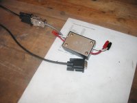
What microcontroller are you using?

Is the throttle graph really throttle or is it current?
I think I'd rather have a bar graph of current.

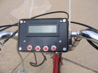
Is the display backlit? I'm sure they make them somewhere.

Nice video too. Next time add some commentary describing what the buttons do.
 
Mathurin: Thanks. I think it is turning out well myself.

knightmb: I'll make a better video in the future and may post it to google video then. This one is a first attempt and the quality is not so great at the end. I may sell them in the future, but right now I actually have to get this thing to work in the real world. Also, thanks for the kudos.

fechter - Thanks. I'm using an Atmel Mega 8. Amazing what they can cram in a 28-pin dip. The throttle bar graph is instantaneous current based on what you entered for max. current on the setting page. I call it throttle because I can't think of a better term. Any ideas? It's basically an efficiency graph so if you keep the bar short, you get longer range. I may examine using power instead depending on how well the current implementation works. I have a backlit display for the prototype hardware, but I'm not going to hook it up until I get everything else working. I'll come up with a better video as I progress. Just wanted to show you guys where I'm at and get some feedback.
 
fechter said:
Next time add some commentary describing what the buttons do.

The meter is set up with four pages, each one may or may not have subpages. The pages are ride, measure, review, and set. The measure page has a subpage that shows volts, amps and watts, and a subpage that shows amp hours and watt hours. The review page has a subpage that shows voltage low and current high statistics, one that shows best amp hours and watt hours, and one that shows total amp hours used and battery cycles. You have the option to add amp hours to the total amp hours when you push the ride reset button on the ride page. The battery cycles are incremented if you are above 2 AH when you hit the ride reset button.

The buttons do the following.

1. Ride Page - Clears ride data (time, volts low, amps high, amp hours, and watt hours) after 2 seconds. You then have a Y/N screen that allows you the option to add your accumulated amp hours to your total amp hours. Battery cycles is incremented if you have exceeded 2 AH.

Set Page - Decrements values.

2. Ride Page - Clears all data after 5 seconds. Set Page - Increments values.

3. Toggles between subpages and moves the asterisk on the set page.

4. Changes between display pages.
 
Looks good. Does what the Brain Drain does, and more.

Ah, but if you can put in a cyclometer function too--and of course, the backlighting!

Great design. Easier to manage pages than the DB--because you have the dedicated buttons.


8)
 
jackatfsi said:
Looks great to me...how about a kit or a set of plans ??? $$ ???

Jack

Hopefully I'll get there. Right now I actually need to have one that I can test on my bike. Not sure about a $$ figure at this time. The printed circuit board will be the most expensive part. I'm gonna do a proto board first and then move on to a printed circuit board.
 
Reid Welch said:
Looks good. Does what the Brain Drain does, and more.

Ah, but if you can put in a cyclometer function too--and of course, the backlighting!

Great design. Easier to manage pages than the DB--because you have the dedicated buttons.


8)

Thanks. It doesn't have all the features of the drain brain. I chose not to implement the regen stuff. I just don't really think you gain that much from regen. Plus, both my bikes have freewheels, so I don't get regen.

I may add a cyclometer function in the future. Bike computers are like $10 and I already have one so it's not a priority right now. As for a backlight, what are you guys, vampires. :) I choose to ride in the light. Haven't tried a night ride yet.

Finally, I'm glad the lcd for my development board came with four switches. It was just the right number and I didn't want to spend my time pushing one button a million times to get to a particular screen.
 
Swordman said:
Reid Welch said:
Looks good. Does what the Brain Drain does, and more.

Ah, but if you can put in a cyclometer function too--and of course, the backlighting!

Great design. Easier to manage pages than the DB--because you have the dedicated buttons.


8)

Thanks. It doesn't have all the features of the drain brain. I chose not to implement the regen stuff. I just don't really think you gain that much from regen. Plus, both my bikes have freewheels, so I don't get regen.

I may add a cyclometer function in the future. Ebike computers are like $10 and I already have one so it's not a priority right now. As for a backlight, what are you guys, vampires. :)

Finally, I'm glad the lcd for my development board came with four switches. It was just the right number and I didn't want to spend my time pushing one button a million times to get to a particular screen.

I could live without the cyclometer. Wal-mart sells good cyclometers for less than $10 and it has worked great on all my e-bikes. If you add a cyclometer function, cool. But getting the nice volts, amps, amp hours, with cool bar graphs would work just fine for me. Start with what you have and perfect that before moving on to a million other functions that we all want to suggest (a USB interface? :wink: , wireless networking, time shifting dimensions)
 
Hi all,

I'm getting closer. I just got back from trying a real-world test. Seems to work fine.

I got hung up for a while on figuring out why my voltage and current readings were not stable when I went from my breadboard system to my on-bike prototype. I created a sensor unit and connected it to the meter unit (pictures below) and instead of 1 or 2 digits hunting (which I would expect), it was hunting more than 10 digits. I fixed this by putting low pass filters on the A/D lines.

If anyone else goes this route, here's some words of wisdom:

1. If the documentation tells you to use low pass filters on your A/D lines to decrease noise, do it. Don't think, hey I don't need to do that.

2. Fixed point math and trying to stay within the machines multiplication and division resolutions is a pain. I still have to fix my current calculation in this area because once it exceeds 3.2 amps it jumps to the max 49.6 amp reading.

I'll spare you the internal box pictures. Suffice it to say, it's on the same level as Xyster's bike. It works well, but is not the most elegant thing in the world. I hope to get my schematic capture stuff done in the near future and have a try at making my own circuit boards.
 

Attachments

  • img_0609_781121851.jpg
    img_0609_781121851.jpg
    75.7 KB · Views: 3,051
  • img_0610_051575578.jpg
    img_0610_051575578.jpg
    50 KB · Views: 3,051
Nice job. I tried to make just a voltmeter and couldn't get the readings to be stable. They were wildy jumping around only when the throttle was twisted, even at no load. Not really even functional. What exactly kind of "low pass filters" did you use? Maybe I'll get another panel meter as they are cheap as mine doesn't work anymore if you can shed some light. It suffered a "spark." My fault.
The complete thread is here:
http://endless-sphere.com/forums/viewtopic.php?t=658&start=30
 
D-Man said:
Nice job. I tried to make just a voltmeter and couldn't get the readings to be stable. They were wildy jumping around only when the throttle was twisted, even at no load. Not really even functional. What exactly kind of "low pass filters" did you use?

Thanks, I hope to have it working totally some day. I had the same experience you did. I set up a breadboard in the house here, got it working with a low current draw, and then said, hey this thing works I think I'll build a prototype. So, I built the prototype, put the prototype on the bike, and it ran fine with the wheel off the ground. Once I went for a ride, the voltage and current readings went all over the place.

Most likely you had the same problem as me, noise coupling into your circuit messing up the reading. This is what the low pass filter is for. You design it for the frequency band you want to pass. For me, I used a 220K ohm resistor and a 0.1 uF capacitor. If you go to this site, they have an online calculator:

http://www.woodsbas.demon.co.uk/calcs/lpfilter.htm
 
It could also be where in the circuit you hooked the meter up. I'm hooking mine between the battery and the controller. If you hooked it on the controller-motor side, you would get a lot of pulses instead of a constant voltage and that could be causing your problem.

One of my first tests, before adding the low pass filters, was to hook the meter between my Astroflight charger and the bike and monitor the voltage while charging. That jumped all over the place probably because of the way the Astroflight does its charging.

I just tried this test again, now that I have the filters in the circuit, and it is rock solid. So, looks like the filter is smoothing the output from the Astroflight.
 
Ok. I have completed the schematic and printed circuit board layout for the sensor unit. I also have created home made circuit boards for the sensor unit using the toner transfer method.

The toner transfer method worked well considering this was my first attempt. Attached are some pictures of the sensor unit and circuit board. Next, I need to clean up the main meter board layout and see how that goes.
 

Attachments

  • board_back.jpg
    board_back.jpg
    45.1 KB · Views: 2,921
  • board_front.jpg
    board_front.jpg
    33.4 KB · Views: 2,921
Hey, lookin' good!
 
Mathurin said:
Hey, lookin' good!

Thanks. I figured I'd start out by making a printed circuit board of the easy part and then move on to the more complicated part once I got this working.
 
fechter said:
What's the current rating on that sensor?

The model I selected can sense currents up to 100 amps unidirectional. It says it can survive 5x overcurrent conditions. The internal resistance is 100 micro ohms. Here's a digikey link:

http://www.allegromicro.com/datafile/0755-100.pdf

I've had it up to 26 amps which is about all my system puts out. I currently have my software and trim resistor settings for 0 to 50 amps, but I may change that in the future.
 
Thanks, I might try one of those for my current mode throttle gizmo.

Actually, the functions of your meter and the current limiting could all be done by a single processor. Might as well throw in temperature activated current limiting and programmable low voltage cutout.

Since DrainBrains seem to be hard to find these days, I really like the idea of building one. Plus I'm cheap.
 
I hope this topic is related enough but it was the closest I could find. I want to purchase a speedometer/cyclometer for an eZee front hub kit modified bicycle. I looked at performancebike.com under cyclocomputers and found a bewildering list of choices. What model would you recommend in the price ranges 1$ to $99, $100 to $199, and $200 and above? I think I would just like a speedometer with memory for things like distance traveled and time, but could be talked into more features. Is it better to go with a wireless or wired model? What is cadence and does this feature make any sense on an e-bike? Is GPS-enabled unit needed, desirable, worth the added cost?

-- Joey
 
Here's the guts of a watts up that met an accidental early death under my foot, I don't know If this helps any, but it might be interesting to look at.IMG_0493.jpg
 
Joey said:
I hope this topic is related enough but it was the closest I could find. I want to purchase a speedometer/cyclometer for an eZee front hub kit modified bicycle. I looked at performancebike.com under cyclocomputers and found a bewildering list of choices. What model would you recommend in the price ranges 1$ to $99, $100 to $199, and $200 and above? I think I would just like a speedometer with memory for things like distance traveled and time, but could be talked into more features. Is it better to go with a wireless or wired model? What is cadence and does this feature make any sense on an e-bike? Is GPS-enabled unit needed, desirable, worth the added cost?

-- Joey
your best bet on the Cycle computer for an electric bike is probably the Cycle Analyst. a couple people sell them, but Ebikes.ca is the OEM, and I don't know if his Ezee controllers come pre wired for them yet or not, but his Crystalyte controllers do. they run $130to $160 depending on your needs and the controller you have. Its literally a hand made device, but its as good as it gets for ebikes. Damn, I sound like a commercial!

cadence is something you realy don't need, its a measurement of how fast your legs are pedaling, in RPM. unless you're training, and have a target cadenceyou want to maintain, then its unimportant.
 
Or for something more basic 'like a speedometer with memory for things like distance traveled and time' the cateye velo5 or velo8 work well & reliably (velo8 also measures time elapsed & average speed for individual trips, but thats only time elapsed/average speed while moving - it stops counting while you are stationary...) and are fairly cheap - £10-15 here so $20US or so?
 
Back
Top